1. Product Overview
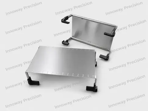
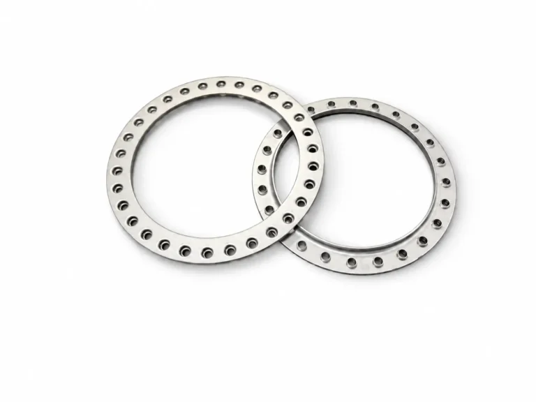
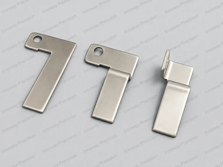
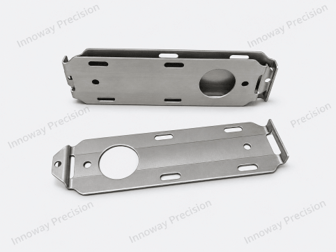
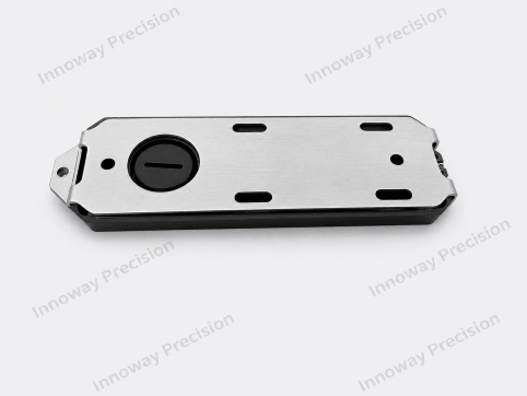
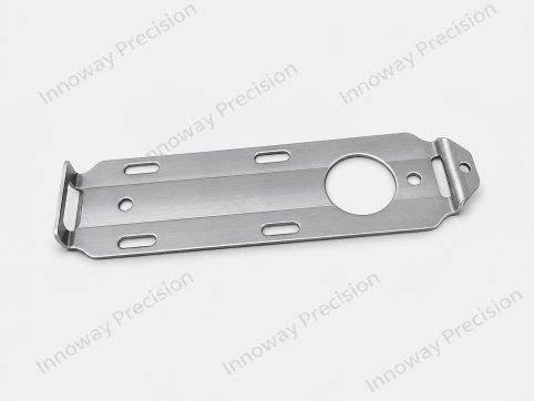
Innoway Precision manufactures this custom bracket from 1.5 mm SUS304-2B stainless steel using progressive die stamping. The part features round holes, elongated slots, and formed ends, with dimensional and surface requirements to support assembly with a mating plastic component.
2. Manufacturing Requirements
Production focuses on consistent hole positions, formed dimensions, controlled burr height, and clean surfaces.
| Feature | Requirement |
|---|---|
| Material | SUS304 stainless steel, 2B finish |
| Thickness | 1.5 mm |
| Manufacturing process | Progressive die stamping |
| Burr height | Maximum 0.05 mm |
| Surface condition | Clean and tidy |
| Assembly fit | Dimensions and formed features must match the approved drawing and mating plastic component |
Cut edges and openings that contact the plastic component require particular attention. In addition to meeting the burr limit, these areas should be checked during trial assembly for interference or scratching.
3. Tooling Design and Durability
A key manufacturing challenge is tooling durability when stamping 1.5 mm SUS304 stainless steel. Inadequate punch and die insert design can lead to premature wear or breakage, affecting part consistency and interrupting production.
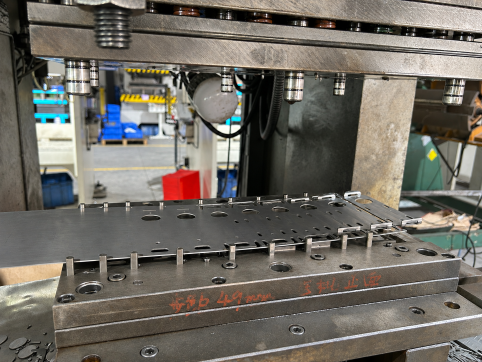
Insert material, heat treatment, cutting clearance, and structural support require careful consideration. During production, monitoring cutting-edge wear and maintaining the tooling are also important for keeping dimensions consistent and burr height within the specified 0.05 mm limit.
Request an OEM Quote
Looking for a similar custom stainless steel bracket? Send Innoway Precision your drawings, order quantity, and assembly requirements for a manufacturing review and quotation.
FAQ
We can achieve ±0.02 mm on selected critical dimensions, subject to drawing review and confirmation before tooling manufacture. This tolerance applies only to explicitly agreed features, rather than every dimension on the bracket. Hole positions, slot dimensions, formed heights and bend angles are inspected against their respective drawing tolerances, with first-article approval required before mass production.
Fit verification requires a physical mating plastic component and the approved assembly drawing. Trial assembly should check seating, hole alignment, engagement of formed features, and any interference or looseness. Contact areas should also be inspected for scratching or damage to the plastic. Dimensional inspection alone does not replace an actual assembly check.
The specified maximum burr height for this bracket is 0.05 mm. Inspection must cover cut edges and hole perimeters, particularly where the metal contacts the plastic. Meeting this limit alone does not confirm that an edge will avoid scratching the plastic. If trial assembly identifies damage or interference, the affected edges require a tighter burr limit or a defined edge-finishing requirement, documented before production approval.
Tooling design must address insert material, heat treatment, cutting clearance and support for vulnerable punch sections. During production, increasing burr height, dimensional drift or chipped edges are triggers for tooling inspection and maintenance. Damaged inserts must be repaired or replaced, and parts produced since the last accepted inspection must be checked. Production should resume only after the tooling and new samples meet the agreed requirements.
These figures require a quotation based on the actual part; no fixed tooling cost, MOQ or lead time is specified for this bracket. To obtain a firm quotation, provide a dimensioned drawing, a 3D file where available, order quantity, expected annual demand and mating-part requirements. The quotation should state the tooling charge, unit price, MOQ, sample lead time and production lead time separately, including when each lead time starts.