1. What Is the Neutral Axis?
Sheet metal bending is a forming process used to change a flat metal sheet into a required angle or shape. During bending, the material around the bend area experiences both compression and tension.
The inner side of the bend is compressed, while the outer side is stretched. Because of this deformation, the bend area cannot be treated as a simple sharp corner when calculating the flat pattern.
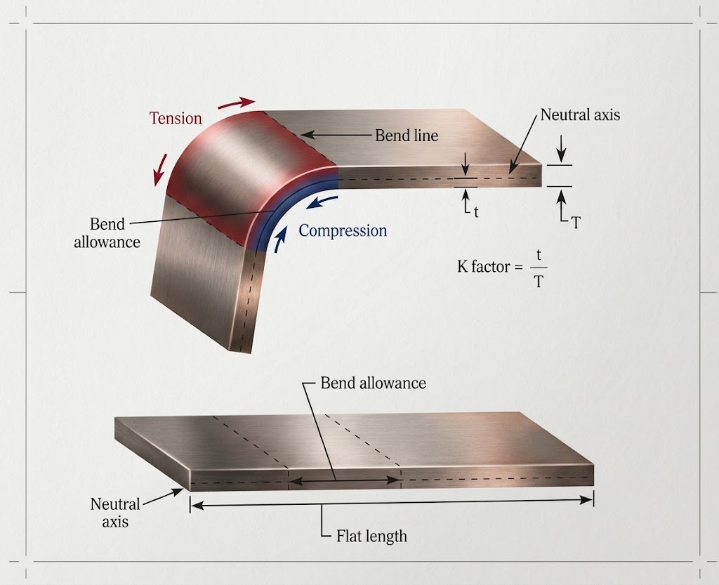
To calculate the correct flat length, we need to understand the neutral axis and Bend Allowance.
When sheet metal is bent, the outer surface stretches and the inner surface compresses. Between these two regions, there is an imaginary layer where the change in length is relatively small. This layer is called the:
Neutral Axis
The neutral axis is located somewhere inside the material thickness, not necessarily at the exact center. Its position is commonly described using the K Factor:
K Factor = Distance from the inside surface to the neutral axis ÷ Material thickness
For example, if:
- Material thickness T = 1.0 mm
- K Factor = 0.33
then the neutral axis is located approximately: 0.33 × 1.0 = 0.33 mm, from the inside surface.
The position of the neutral axis is important because the developed bend length is calculated along this layer.
2. What Is Bend Allowance?
Bend Allowance, commonly abbreviated as BA, is: The length of the neutral axis through the bend area when the sheet metal is flattened. In simple terms, when a curved bend is unfolded into a flat sheet, the bend area becomes a straight length.
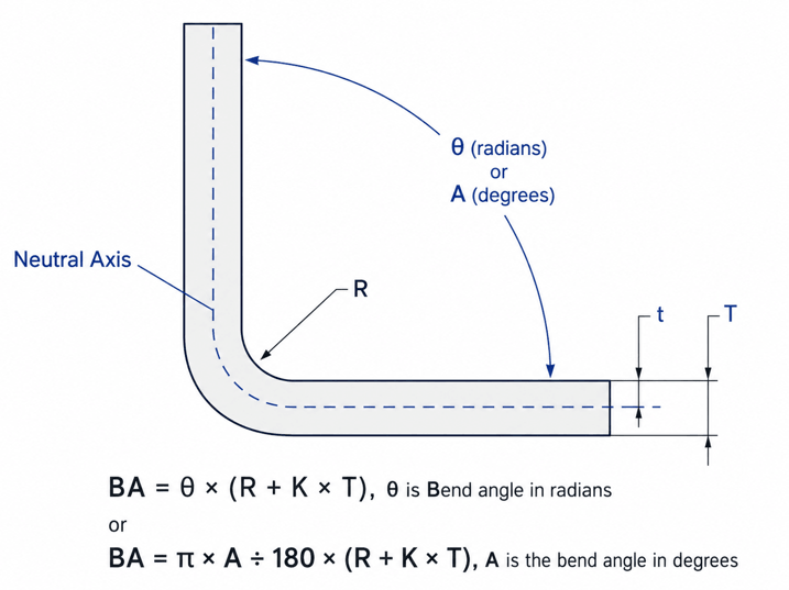
That length is the Bend Allowance. The common formula is: BA = θ × (R + K × T), Where:
- BA = Bend Allowance
- θ = Bend angle in radians
- R = Inside bend radius
- K = K Factor
- T = Material thickness
If the bend angle is given in degrees, the formula can also be written as:
BA = π × A ÷ 180 × (R + K × T), Where A is the bend angle in degrees.
3. Bend Allowance Calculation Example
Assume the following conditions:
- Material: SPCC
- Thickness T = 1.0 mm
- Inside bend radius R = 1.0 mm
- K Factor = 0.33
- Bend angle = 90°
The formula is: BA = π × 90 ÷ 180 × (1 + 0.33 × 1), So: BA = 1.5708 × 1.33
Therefore: BA ≈ 2.09 mm. This means the neutral axis through the 90-degree bend has a developed length of approximately: 2.09 mm. When calculating the flat pattern, this bend region must be included in the total developed length.
4. Why Bend Allowance Matters
Bend Allowance directly affects flat pattern accuracy. If the Bend Allowance is incorrect, the final bent part may have problems such as:
- Incorrect overall dimensions
- Hole position errors
- Assembly interference
- Incorrect welding gaps
- Poor fit between mating parts
For production work, the K Factor and bend radius should ideally be verified based on the actual material, tooling, and bending process used in the factory.
FAQ
Bend Allowance is the developed length of the neutral axis through the bend region of a sheet metal part.
A commonly used formula is: BA = θ × (R + K × T), where θ is the bend angle in radians, R is the inside bend radius, K is the K Factor, and T is the material thickness.
The neutral axis is a layer inside the sheet thickness where the change in length during bending is relatively small.
K Factor describes the position of the neutral axis within the material thickness.
Yes. A larger inside bend radius generally increases the Bend Allowance.
No. A K Factor of 0.33 is commonly used as a reference value, but the actual value can vary depending on material, thickness, tooling, and bending conditions.
Sheet metal development mainly focuses on calculating the unfolded length of bends based on parameters such as material thickness, bend radius, neutral axis, and K Factor.
Stamping development is usually more complex because it may involve material flow, drawing, stretching, forming, trimming, springback, and multiple die stages.