1. Why Self-Clinching Fastener Design Matters
A self-clinching fastener that spins, loosens or falls out during assembly can cause far more damage than the cost of the fastener itself. For finished sheet metal assemblies, one failed attachment can lead to rework, production delays or costly field repairs.
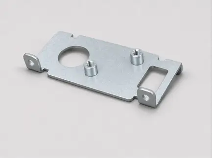
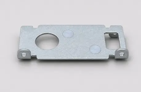
This guide focuses on custom self-clinching fasteners, including custom clinch nuts, with a knurled feature and an annular locking undercut. Drawing on Innoway Precision’s manufacturing experience, it explains how hole clearance, undercut depth and height, and knurl dimensions influence torque-out and push-out resistance.
These dimensions are experience-based starting points for custom fastener development, not universal specifications or substitutes for a standard fastener manufacturer’s requirements. Validate each design using the intended sheet material, thickness and installation process against the agreed torque-out and push-out criteria.
2. What Makes a Reliable Self-Clinching Connection?
A fastener that sits flush and feels secure by hand has not necessarily formed a reliable connection. Two key performance measures are torque-out resistance and push-out resistance.
| Performance measure | Typical failure symptoms | Potential customer impact |
|---|---|---|
| Torque-out resistance: resistance to rotation within the sheet | The fastener spins during tightening or turns with the mating component during removal | Assembly interruptions, difficult servicing and potentially destructive removal |
| Push-out resistance: resistance to axial removal opposite the installation direction | The fastener shifts, loosens or separates from the sheet under axial force | Rework, replacement and equipment disassembly; loose metal hardware may also damage internal components |
Inconsistent retention across a production batch can require extensive sorting or stop a customer’s assembly line. If failures appear after delivery, the costs may include return shipments, replacement assemblies and on-site repairs.
The underlying issue is whether installation creates an effective mechanical interlock.
During clinching, local pressure causes the sheet material to flow plastically into the locking undercut and engage the knurled feature:
- The knurl primarily resists rotation.
- The material captured in the undercut primarily provides axial retention.
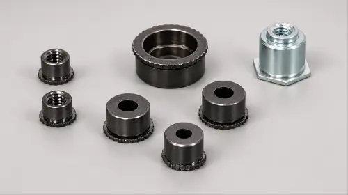
These features work together. Their effectiveness depends on the available sheet material and how that material moves during installation. www.pemnet.com
3. How Much Clearance Should the Mounting Hole Have?
Our manufacturing guideline is a diametral clearance of no more than 0.10 mm, while maintaining proper insertion.
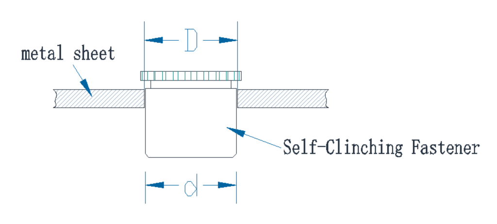
Let:
- D = mounting hole diameter.
- d = locating shank diameter, excluding the knurl.
Diametral clearance = D − d ≤ 0.10 mm
This is the difference between the two diameters—not the clearance on each side. When the shank is centered, a 0.10 mm diametral clearance corresponds to a 0.05 mm radial gap per side.
| Clearance condition | Possible effect |
|---|---|
| Too large | Poor positioning and potentially insufficient material engagement or undercut filling |
| Too small | Difficult insertion, hole-wall scraping or local deformation if the fastener is forced into place |
| Properly matched | Consistent positioning and suitable conditions for material flow into the retention features |
The goal is to allow convenient placement while preserving enough material around the hole to form the interlock.
4. How Deep and High Should the Locking Undercut Be?
For the custom self-clinching designs commonly used in our production, radial undercut depth is typically 0.20–0.30 mm, and axial undercut height is 0.45–0.55 mm.
| Dimension | Measurement direction | Manufacturing guideline |
|---|---|---|
| Radial undercut depth | From the adjacent shank surface inward to the groove root | 0.20–0.30 mm |
| Axial undercut height | Between the upper and lower groove boundaries, along the fastener axis | 0.45–0.55 mm |
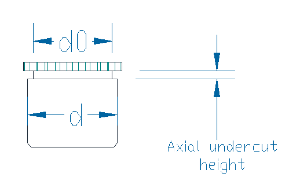
Let d be the adjacent shank diameter and d0 the groove root diameter:
Radial undercut depth = (d − d0) ÷ 2
The undercut provides space for displaced sheet material and forms a mechanical interlock that resists axial removal. Its depth and height must be matched to the sheet thickness and the amount of material displaced during installation.
An excessively deep or tall undercut can be difficult to fill.
Increasing the groove volume does not increase the available sheet material. Incomplete filling may limit the effectiveness of the retaining geometry.
An excessively shallow or short undercut can provide insufficient space.
For an unchanged displacement feature, this may contribute to local material buildup, panel bulging or deformation around the hole.
The objective is to provide adequate retention geometry and sufficient material to fill it effectively.
For custom designs, section installed samples to inspect undercut filling, then verify push-out resistance against the agreed acceptance requirements. These dimensions are Innoway Precision’s manufacturing guidelines and require validation with the intended sheet material, thickness and installation process.
5. How Much Larger Should the Knurl Be Than the Shank?
Our manufacturing guideline is a radial knurl projection of 0.25–0.50 mm beyond the shank on each side.
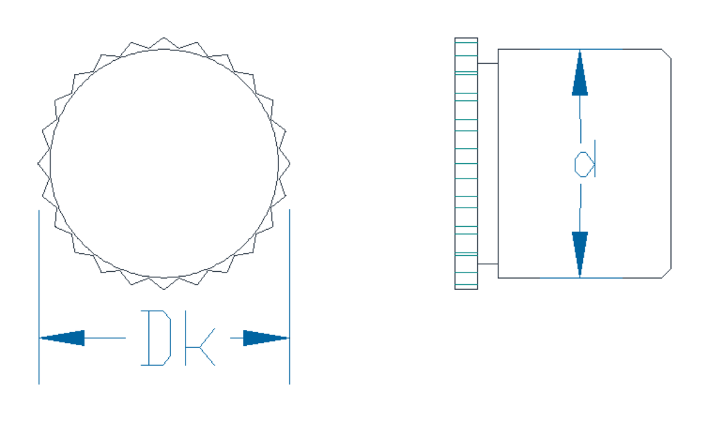
Let:
- Dk = knurl outside diameter.
- d = shank diameter.
Radial projection = (Dk − d) ÷ 2 = 0.25–0.50 mm.
This means the knurl outside diameter is 0.50–1.00 mm larger than the shank diameter.
Radial projection is a geometric dimension. It is not the actual depth of engagement with the sheet, which also depends on the mounting hole, tooth geometry and installed position.
| Knurl condition | Possible effect |
|---|---|
| Insufficient projection | Inadequate engagement and material displacement, potentially reducing torque-out resistance and undercut filling |
| Excessive projection | Excessive local displacement, higher installation loads and greater risk of panel distortion |
| Properly matched geometry | Effective rotational engagement and controlled material flow toward the undercut |
For the fastener structure discussed here, the knurl also acts as a displacement feature, pushing sheet material toward the undercut during installation. Knurl geometry and undercut volume must therefore be designed together. www.pemnet.com
Tooth count, tooth profile and knurl height also affect performance. Increasing the outside diameter alone does not guarantee greater torque-out resistance.
Use these three dimensions as coordinated design inputs:
| Design parameter | Innoway Precision manufacturing guideline |
|---|---|
| Hole-to-shank diametral clearance | ≤0.10 mm, with proper insertion |
| Radial undercut depth | 0.20–0.30 mm |
| Radial knurl projection beyond the shank | 0.25–0.50 mm per side |
Validate the design using the intended production sheet material. Inspect seating, material filling and panel distortion, then measure torque-out and push-out resistance against the agreed acceptance requirements.
A reliable design must consistently meet the required retention performance under the specified material and installation conditions.
Frequently Asked Questions
No. In this guide, it means the mounting hole diameter minus the locating shank diameter. A centered 0.10 mm diametral clearance produces a 0.05 mm radial gap per side.
No. If insufficient sheet material enters the undercut, additional depth may not improve retention. Undercut depth must be matched to groove width, sheet thickness and material displacement.
No. An oversized knurl may cause excessive displacement and panel distortion. Performance also depends on tooth geometry and the engagement achieved during installation.
Adjusting the process may help if the fastener is not fully installed. However, additional force cannot reliably compensate for an incorrect hole, unsuitable retention geometry or incompatible material.