1. Project Overview
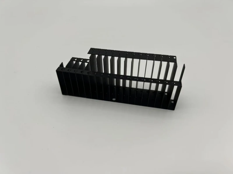
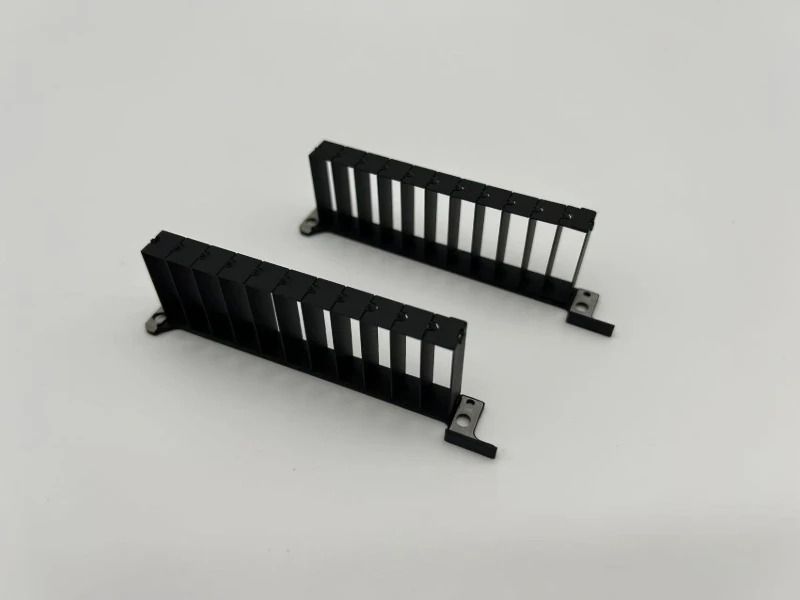
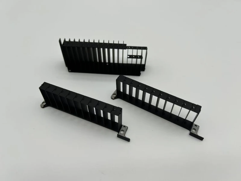
This project involved a custom zipper fin heat sink for GPU cooling. The heat sink uses multiple thin metal fins assembled at a controlled pitch to create a large heat-transfer area while maintaining an open airflow path.
Unlike a conventional extruded heat sink, this design uses individually formed fins with interlocking features. The fin stack is then integrated with mounting structures so it can be installed accurately inside the GPU cooling assembly.
For this type of part, the challenge is not simply producing each fin. The real challenge is keeping dozens of thin fins consistent after stamping and assembly.
2. The Challenge: Thin Fins Make Small Errors Add Up Quickly
GPU cooling components are sensitive to airflow and contact efficiency. Several manufacturing issues had to be controlled.
2.1 Fin Pitch Consistency
Each fin must maintain a stable spacing. If individual fins shift only slightly during forming or assembly, the accumulated error across the entire fin stack can become significant. Uneven spacing can also disturb airflow through the heat sink.
2.2 Thin Fin Deformation
Thin stamped fins can easily: bend, twist, buckle, or become damaged during handling. Once assembled, correcting a distorted fin stack is much more difficult.
2.3 Interlocking Accuracy
The zipper-style structure depends on small stamped locking features. If the forming position or angle is unstable, the fins may not lock correctly, resulting in:
- inconsistent fin spacing
- weak assembly
- excessive overall length
- or visible misalignment
2.4 Mounting Alignment
The heat sink is eventually installed into a GPU cooling system. Therefore, the mounting points must remain correctly positioned relative to the fin stack. A heat sink with good-looking fins but incorrect mounting dimensions is still an unusable part.
3. Our Manufacturing Solution
3.1 Precision Stamping for Repeatable Fin Geometry
The fin structure is produced by controlled stamping and forming operations.
Instead of relying on secondary manual adjustment, the forming sequence is designed to control the critical geometry directly during production, including:
- fin profile
- interlocking features
- forming angle
- and fin positioning features
For high-volume production, this approach provides much better consistency than individually forming and adjusting each fin manually.
3.2 Interlocking Fin Stack Assembly
After forming, individual fins are assembled into a zipper fin stack.
The interlocking structure helps control the relative position between adjacent fins and keeps the fin pitch consistent throughout the assembly.
The key control point is not only whether the fins can be connected, but whether the entire stack remains straight after dozens of fins are assembled.
3.3 Dedicated Fixture for Final Dimensional Control
A dedicated fixture is used during assembly and inspection to control: Overall Length + Fin Pitch + Straightness + Mounting Position.
This is especially important because tolerance accumulation is one of the most common issues in long fin-stack structures.
Rather than inspecting only individual fins, we also control the dimensions of the complete assembled heat sink.
3.4 Surface and Appearance Control
Because GPU cooling components are often visible during final assembly, handling marks, bent fins and surface defects need to be minimized.
The finished heat sink therefore requires careful control during: Stamping → Transfer → Assembly → Surface Treatment → Packing. For thin-fin products, improper handling can create more defects than the stamping process itself.
4. The Result
By controlling both the individual stamped fins and the complete fin stack, the finished GPU heat sink achieved:
- consistent fin spacing
- stable interlocking
- good overall straightness
- accurate mounting dimensions
- clean fin appearance
- and repeatable production quality
More importantly, the manufacturing process is suitable for stable batch and mass production, rather than depending heavily on manual adjustment.
For GPU thermal components, this repeatability is critical. Cooling performance starts with thermal design, but it still depends on whether the physical heat sink can be manufactured consistently.
5. Why Zipper Fin Heat Sinks Are Used in GPU Cooling
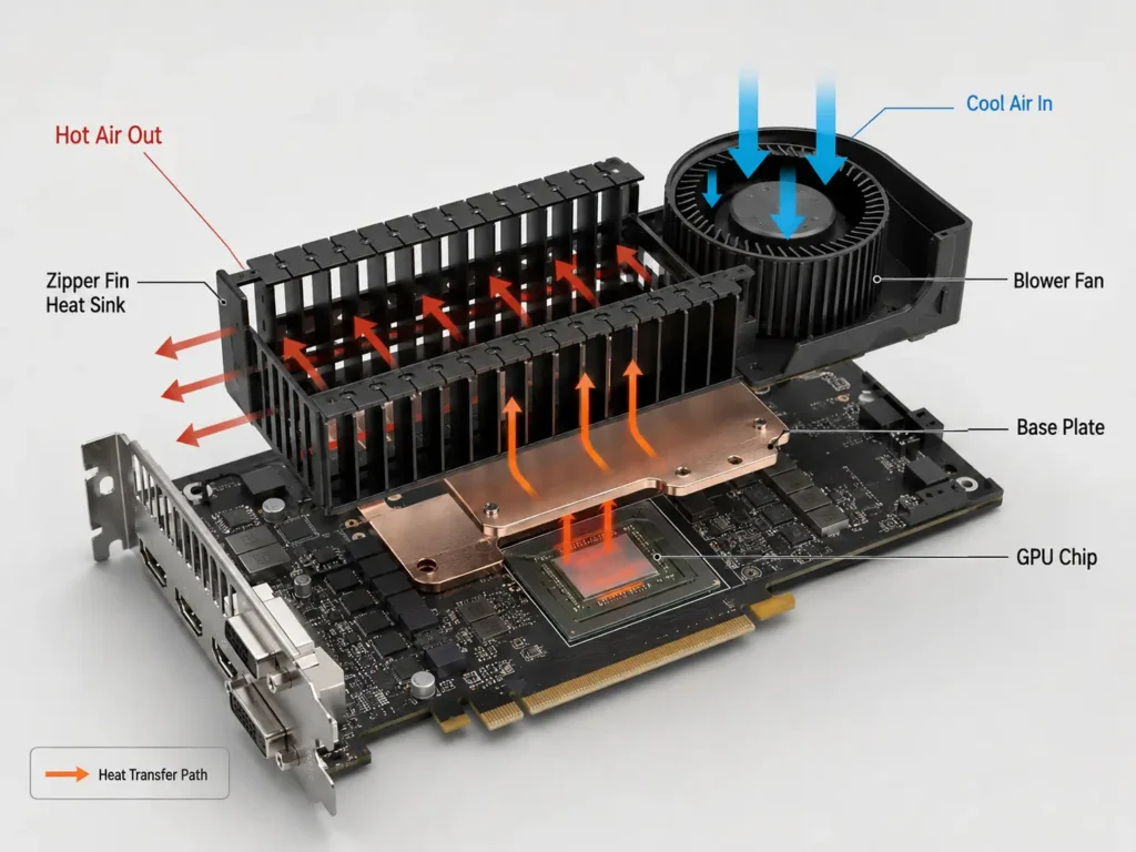
A zipper fin structure allows manufacturers to use thin, closely controlled metal fins to obtain a high surface area within a limited space. Compared with some conventional heat sink structures, stamped fin stacks also provide greater flexibility in:
- fin height
- fin pitch
- airflow channel design
- heat pipe integration
- mounting structure
- and overall heat sink geometry
This makes them suitable for compact, high-power electronic cooling applications such as GPUs.
6. Custom GPU Heat Sink Manufacturing
At Innoway Precision, we support custom metal components for thermal management applications, including: Precision stamping · Fin forming · Zipper fin assembly · Sheet metal fabrication · Fixture development · Secondary assembly.
If you are developing a GPU heat sink, power electronics cooling component or other custom fin-stack product, we can review your drawings and provide manufacturing feedback before mass production.
Website: www.innoway-metalparts.com
Email: sales@innoway-metalparts.com
Frequently Asked Questions
A zipper fin heat sink is made from multiple thin stamped metal fins that use interlocking features to connect and maintain a controlled fin spacing. The assembled structure is commonly called a zipper fin stack.
They allow a large heat-transfer surface area to be packed into a relatively small space while maintaining airflow channels between the fins, making them suitable for high-power GPU cooling systems.
Depending on the design, fins can be produced by precision stamping, progressive die forming and secondary forming operations. They are then assembled into a fin stack and integrated with other heat sink components.
Fin spacing is controlled through the stamped geometry, interlocking features and dedicated assembly fixtures. The complete fin stack should also be inspected because small individual tolerances can accumulate across many fins.
Aluminum and copper are commonly used because of their good thermal conductivity. Material selection depends on cooling requirements, weight, cost and the overall heat sink design.
An extruded heat sink is produced from an aluminum extrusion profile, while a zipper fin heat sink uses multiple individually formed thin fins assembled together. Zipper fin designs generally offer greater flexibility for thin fins, high fin density and complex cooling structures.