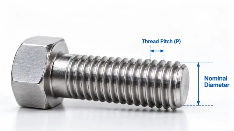
1. What Are Self-Clinching Fasteners?
Self-clinching fasteners provide permanent internal threads, external threads or fixed spacing in thin sheet metal. This guide compares self-clinching nuts, threaded studs, through-hole standoffs and blind standoffs, with metric mounting-hole sizes, minimum sheet thicknesses, edge distances and installation requirements based on the referenced domestic supplier specifications.
They are widely used in server chassis, telecommunications equipment, electrical enclosures, automotive electronics, medical devices, and precision sheet metal assemblies.
The dimensions in this guide apply only to the corresponding supplier products. PEM specifications are provided as an additional engineering reference and should not be treated as dimensionally interchangeable without verification.
1.1 Self-Clinching Nuts, Studs and Standoffs Compared
A self-clinching fastener is mechanically locked into a sheet through localized plastic deformation. During installation, displaced sheet material flows into the annular undercut beneath the clinching feature, producing permanent resistance to rotation and pushout.
| Product category | Common types | Structure provided | Typical applications |
|---|---|---|---|
| Self-clinching nut | S, CLS, SP, CLA | Internal thread | Screw attachment in thin sheet |
| Threaded stud | FH, FHS | Fixed external thread | Brackets, PCBs, and components |
| Through-hole standoff | SO, SOS, SOA | Through thread and fixed spacing | PCBs and multi-level assemblies |
| Blind standoff | BSO, BSOS, BSOA | Closed thread and fixed spacing | Controlled screw depth and component protection |
In the Chinese supply chain, FH/FHS products and SO/BSO products may all be called “self-clinching studs.” In this guide, FH/FHS are described as threaded studs, while SO/BSO products are described as standoffs.
1.2 How Self-Clinching Fasteners Work
The fastener is placed in a controlled mounting hole and installed with a press or dedicated insertion machine. As a perpendicular squeezing force is applied, sheet material cold-flows into the annular undercut. The undercut resists pushout, while serrations or ribs resist rotation.
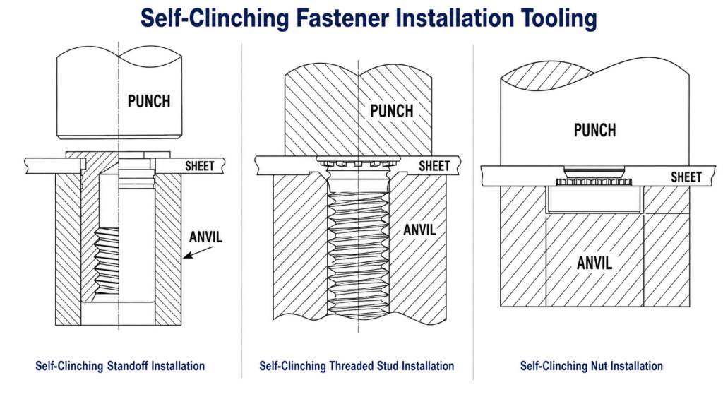
The clinching section must be harder than the receiving sheet, and the sheet hardness must remain within the supplier’s specified limit. Incorrect hole size, insufficient sheet thickness, excessive sheet hardness, inadequate tooling support, or improper force can cause rotation, low pushout strength, sheet bulging, thread damage, or fastener tilting.
2. Common Types, Materials, and Installation Dimensions
All dimensions are in millimeters and are based on the attached domestic supplier specifications. “Minimum edge distance” means the distance from the mounting-hole centerline to a straight, free sheet edge. Dimension symbols must be interpreted according to the drawing for the relevant product family. The same letter may have different meanings in different drawings.
2.1 Self-Clinching Nuts: S, CLS, SP, and CLA
Self-clinching nuts provide permanent internal threads in thin metal sheets. During installation, displaced sheet material flows into the annular undercut beneath the clinching ring, creating resistance to both rotation and pushout.
The four common material types are S carbon steel, CLS stainless steel, SP hardened stainless steel, and CLA aluminum. Material selection must consider the hardness of the receiving sheet. A stainless steel fastener is not automatically suitable for stainless steel sheet; the clinching section must be sufficiently harder than the panel.
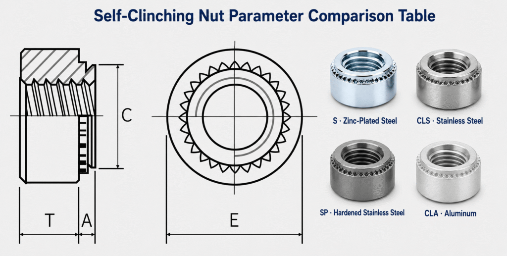
In the corresponding drawing:
- C is the maximum diameter of the clinching section;
- E is the maximum outside diameter of the nut;
- T is the overall nut thickness.
Domestic self-clinching nuts are normally designated by type, thread size, and shank code. For example, S-M4-1 indicates a carbon steel S-type nut with an M4×0.7 internal thread and shank code 1. According to the table, it requires a minimum sheet thickness of 1.0 mm, a Ø5.40 0+0.08 mounting hole, and a minimum edge distance of 6.9 mm.
Self-Clinching Nut Types and Installation Dimensions(Unit: mm)
| Thread size | Carbon steel | Stainless steel | Hardened SS | Aluminum | Shank code | A max. | Min. sheet | Hole +0.08/0 | C max. | E ±0.25 | T ±0.1 | Min. edge |
|---|---|---|---|---|---|---|---|---|---|---|---|---|
| M2×0.4 | S | CLS | SP | CLA | 012 | 0.76 0.97 1.37 | 0.8 1.0 1.4 | 4.25 | 4.22 | 6.35 | 1.50 | 4.8 |
| M2.5×0.45 | S | CLS | SP | CLA | 012 | 0.76 0.97 1.37 | 0.8 1.0 1.4 | 4.25 | 4.22 | 6.35 | 1.50 | 4.8 |
| M3×0.5 | S | CLS | SP | CLA | 0123 | 0.76 0.97 1.37 2.21 | 0.8 1.0 1.4 2.3 | 4.25 | 4.22 | 6.35 | 1.50 | 4.8 |
| M3.5×0.6 | S | CLS | SP | CLA | 012 | 0.76 0.97 1.37 | 0.8 1.0 1.4 | 4.75 | 4.73 | 7.00 | 1.50 | 5.6 |
| M4×0.7 | S | CLS | SP | CLA | 0123 | 0.76 0.97 1.37 2.21 | 0.8 1.0 1.4 2.3 | 5.40 | 5.38 | 7.95 | 2.00 | 6.9 |
| M5×0.8 | S | CLS | SP | CLA | 0123 | 0.76 0.97 1.37 2.21 | 0.8 1.0 1.4 2.3 | 6.40 | 6.38 | 8.65 | 2.00 | 7.1 |
| M6×1.0 | S | CLS | SP | CLA | 000123 | 0.89 1.15 1.37 2.21 3.05 | 0.92 1.2 1.4 2.3 3.18 | 8.75 | 8.72 | 11.05 | 4.08 | 8.6 |
| M8×1.25 | S | CLS | SP | CLA | 0123 | 1.15 1.37 2.21 3.05 | 1.2 1.4 2.3 3.18 | 10.50 | 10.47 | 12.65 | 5.47 | 9.7 |
| M10×1.5 | S | CLS | SP | CLA | 0123 | 1.61 2.21 3.05 3.84 | 1.7 2.3 3.18 4.0 | 14.00 | 13.97 | 17.35 | 7.48 | 13.5 |
| M12×1.75 | S | CLS | SP | CLA | 012 | 2.48 3.05 3.84 | 2.5 3.18 4.0 | 17.00 | 16.97 | 20.05 | 8.50 | 18.0 |
The shank codes and minimum sheet thicknesses correspond in the same sequence. For example, M4 codes 0, 1, 2, and 3 correspond to minimum sheet thicknesses of 0.8, 1.0, 1.4, and 2.3 mm respectively.
The shank code identifies the clinching-length range rather than the overall nut height. It must be selected according to the actual sheet thickness so that sufficient sheet material can flow into the annular undercut.
2.2 Self-Clinching Threaded Studs: FH and FHS
FH carbon steel and FHS stainless steel studs provide a permanently mounted external thread. They are commonly used for brackets, PCBs, covers, and internal assemblies.
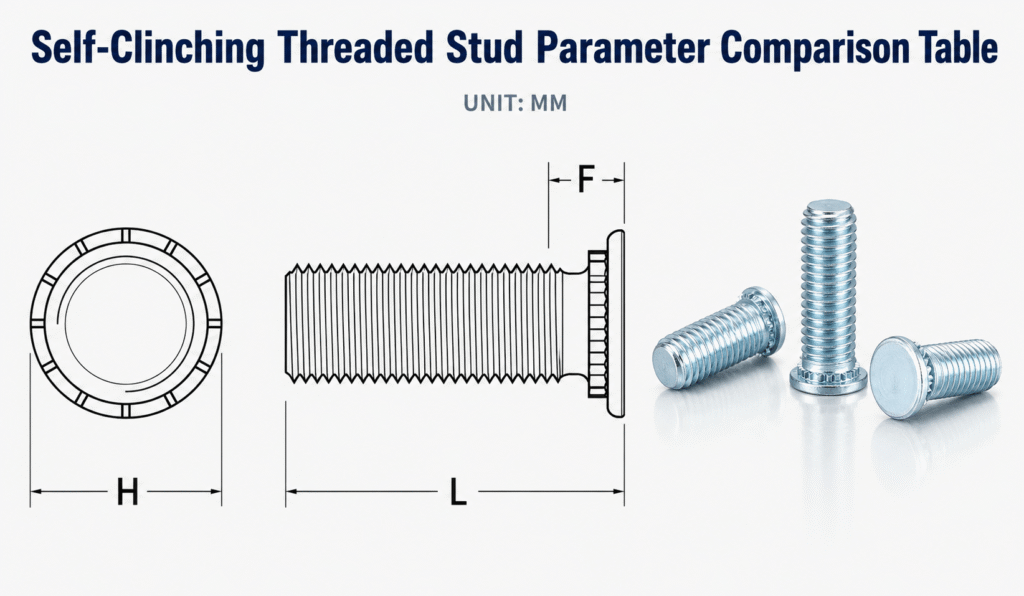
H represents the clinching head diameter, F the incomplete or unthreaded region near the head, and L the nominal stud length. FH-M4-10 indicates an FH carbon steel stud with an M4×0.7 external thread and a nominal length of 10 mm.
FH/FHS Installation Dimensions:
| Thread size | Carbon steel | Stainless steel | Minimum sheet thickness | Mounting hole | Head diameter H | F maximum | Minimum edge distance |
|---|---|---|---|---|---|---|---|
| M2.5×0.45 | FH | FHS | 1.0 | Ø2.50 | 4.1 | 1.95 | 5.4 |
| M3×0.5 | FH | FHS | 1.0 | Ø3.00 | 4.6 | 2.10 | 5.6 |
| M4×0.7 | FH | FHS | 1.0 | Ø4.00 | 5.9 | 2.40 | 7.2 |
| M5×0.8 | FH | FHS | 1.0 | Ø5.00 | 6.5 | 2.70 | 7.2 |
| M6×1.0 | FH | FHS | 1.6 | Ø6.00 | 8.2 | 3.00 | 7.9 |
| M8×1.25 | FH | FHS | 2.4 | Ø8.00 | 9.6 | 3.70 | 9.6 |
The mounting hole remains a controlled clinching hole even though its diameter is close to the nominal thread size. A standard bolt clearance hole must not be substituted.
Dimension F must be considered when calculating usable thread length because this region does not provide complete thread engagement.
2.3 Through-Hole and Blind Standoffs
SO, SOS, and SOA are through-hole standoffs. BSO, BSOS, and BSOA are blind standoffs with a closed threaded end.
| Structure | Carbon steel | Stainless steel | Aluminum | Main function |
|---|---|---|---|---|
| Through-hole | SO | SOS | SOA | Fixed spacing with a through-threaded hole |
| Blind | BSO | BSOS | BSOA | Fixed spacing with controlled screw penetration |
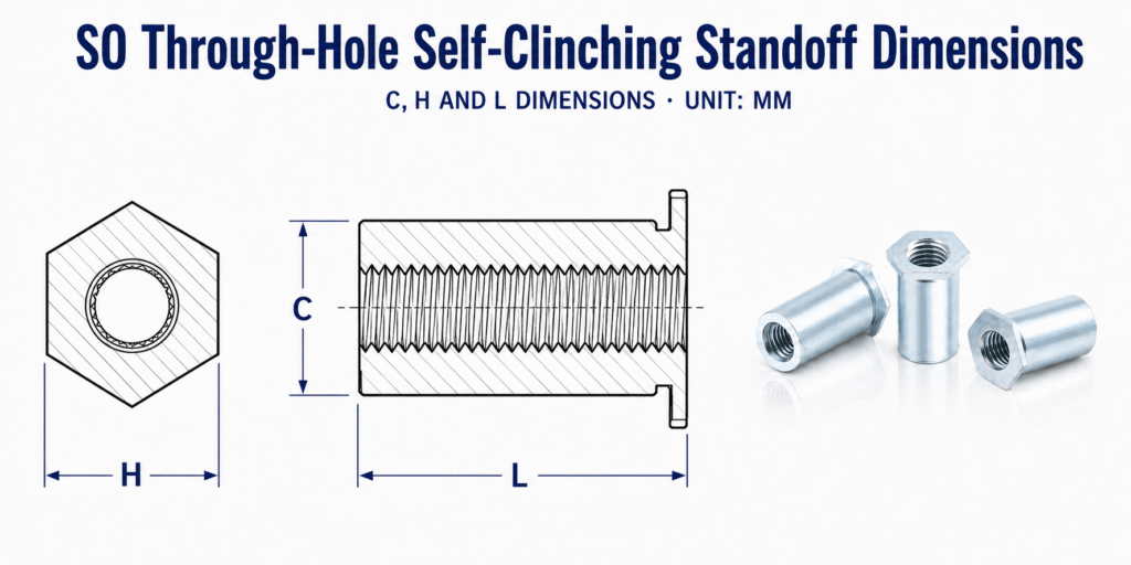
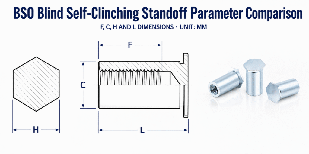
C represents the clinching-section diameter, H the external body dimension, and L the nominal standoff length. F represents the minimum effective thread depth of a blind standoff. For common metric BSO series:
- L = 6 mm: F ≥ 3.2 mm
- L = 8 or 10 mm: F ≥ 4.0 mm
- L = 12 mm: F ≥ 5.0 mm
- L = 14 or 16 mm: F ≥ 6.5 mm
- L = 18, 20, 22, or 25 mm: F ≥ 9.5 mm
Specifications may vary between domestic suppliers. Final production dimensions should be based on the approved supplier drawing.
SO-M3-8 identifies an M3×0.5 through-hole standoff with an 8 mm nominal length.
BSO-M3-8 identifies the corresponding blind version.
The two structures use the same mounting dimensions in the attached supplier tables, so they are combined below.
Standoff Installation Dimensions
| Thread/structure code | Carbon steel | Stainless steel | Aluminum | Minimum sheet thickness | Mounting hole | C dimension | H dimension | Minimum edge distance |
|---|---|---|---|---|---|---|---|---|
| M2×0.4 | SO/BSO | SOS/BSOS | SOA/BSOA | 1.0 | Ø4.22 | 4.20 | 4.8 | 6.0 |
| M2.5×0.45 | SO/BSO | SOS/BSOS | SOA/BSOA | 1.0 | Ø4.22 | 4.20 | 4.8 | 6.0 |
| M3×0.5 | SO/BSO | SOS/BSOS | SOA/BSOA | 1.0 | Ø4.22 | 4.20 | 4.8 | 6.0 |
| 3.5M3×0.5 | SO/BSO | SOS/BSOS | SOA/BSOA | 1.0 | Ø5.41 | 5.39 | 6.4 | 6.8 |
| M4×0.7 | SO/BSO | SOS/BSOS | SOA/BSOA | 1.3 | Ø6.00 | 5.98 | 7.0 | 7.5 |
| 3.5M4×0.7 | SO/BSO | SOS/BSOS | SOA/BSOA | 1.3 | Ø7.14 | 7.12 | 7.9 | 8.0 |
| M5×0.8 | SO/BSO | SOS/BSOS | SOA/BSOA | 1.3 | Ø7.14 | 7.12 | 7.9 | 8.0 |
| M6×1.0 | SO/BSO | SOS/BSOS | SOA/BSOA | 1.3 | Ø8.72 | 8.70 | 10.0 | 10.0 |
“3.5M3” and “3.5M4” are supplier-specific heavy-wall structure codes, not standard M3.5 threads. The complete code must be retained on engineering drawings and purchase orders.
For blind standoffs, the drawing must also specify the effective thread depth and maximum permitted screw penetration. The screw must not bottom out before the joint is fully tightened.
2.4 Mounting-Hole and Installation Requirements
| Control item | Requirement |
|---|---|
| Hole diameter | Follow the specified value and tolerance |
| Hole shape | Keep the hole round and free from punching distortion |
| Hole edge | Do not countersink, chamfer, or excessively deburr |
| Installation equipment | Use a press or dedicated insertion machine |
| Force direction | Keep the punch and anvil parallel to the sheet |
| Tooling support | Fully support the sheet around the fastener |
| Installation method | Do not use hammers or impact tools |
If punching produces excessive burrs, correct the punching clearance or worn tooling instead of enlarging the hole through secondary deburring.
Insufficient insertion force results in incomplete undercut filling and low retention strength. Excessive force can deform the thread, buckle the sheet, or tilt the fastener.
Before mass production, verify head seating, perpendicularity, thread gauging, sheet deformation, pushout resistance, torque-out resistance, and actual screw engagement using production materials and tooling.
2.5 Design Near Edges, Bends, and Formed Features
The listed minimum edge distance applies to one fastener near one straight, free sheet edge. Additional clearance is required near bends, flanges, reinforcing ribs, embossments, or other fasteners.
Use the following symbols:
- D: mounting-hole diameter;
- t: sheet thickness;
- e: hole centerline-to-edge distance;
- b: hole centerline-to-bend tangent or formed-feature root;
- P: center distance between fasteners.
When supplier-specific bend data are unavailable, use:
| Fastener size | Recommended centerline-to-bend tangent distance |
|---|---|
| M2–M4 | 6–8 mm |
| M5–M6 | 8–12 mm |
| M8 and larger | Confirm according to fastener and tooling size |
The complete clinching area must remain on a flat surface and outside the bend radius or formed transition. Sufficient punch and anvil clearance must also be provided. PEM Centerline-to-Edge Technical Sheet
For fasteners close to a bend, the recommended sequence is:
Bend the sheet → inspect or calibrate the mounting hole → install the fastener.
For two adjacent fasteners of the same size:For different mounting-hole diameters:If space is insufficient, relocate the fastener or use a supplier-approved low-displacement product. Increasing the insertion force does not correct inadequate spacing and may cause sheet bulging or thread damage.
3. PEM References and Technical Disclaimer
PEM documentation provides product-specific mounting holes, minimum sheet thicknesses, edge distances, permitted sheet hardness, tooling information, and reference performance data.
When a genuine PEM product is specified, use the latest PEM documentation rather than the domestic dimensions in this guide.
Official PEM References
- PEM Self-Clinching Nuts
- PEM Self-Clinching Threaded Studs
- PEM Self-Clinching Standoffs
- PEM Self-Clinching Fastener Handbook
- PEM Centerline-to-Edge Technical Sheet
- PEM Complete Fastener Catalog
PEM® is a registered trademark of PennEngineering. References to PEM do not indicate that the domestic products listed in this guide are genuine PEM products or dimensionally and mechanically equivalent.
FAQ
Self-clinching fasteners are permanently pressed into ductile sheet metal. During installation, displaced sheet material flows into the fastener’s undercut groove, providing axial retention, while serrations resist rotation.
Self-clinching nuts provide internal threads, FH/FHS studs provide fixed external threads, and SO/BSO standoffs provide internal threads with a defined spacing height. SO types are through-threaded, while BSO types have a closed blind end.
The mounting hole must follow the exact product series and supplier specification. Fasteners with the same thread size may require different hole diameters and tolerances, so standard bolt-clearance holes must not be substituted.
Match the shank code to the actual sheet thickness and the supplier’s minimum sheet-thickness requirement. The code identifies the clinching shank length, not the nut’s overall height.
Not always. The sheet must be sufficiently ductile and softer than the fastener’s clinching section. For stainless steel sheets, use a series specifically approved for the applicable sheet hardness, such as SP where specified.
Common causes include an incorrect hole size, insufficient sheet thickness, excessive sheet hardness, improper press force, misaligned tooling, or inadequate edge distance. Production should begin only after installation and performance testing on the actual sheet material.