Six Common Types of Holes in Engineering
Holes in mechanical parts are designed for more than simply passing a screw through the material. Different types of holes in engineering provide different functions, including fastening, positioning, load distribution, clearance, sealing and torque transmission.
This guide explains six common hole features: counterbore, countersink, spotface, through hole, blind hole and square hole.
1. Counterbore Hole
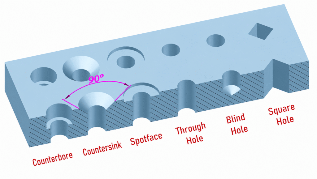
A counterbore hole consists of a smaller main hole and a larger cylindrical recess machined concentrically above it. The enlarged section has straight sidewalls and a flat bottom.
Its primary purpose is to accommodate a socket-head cap screw, cylindrical screw head, hex bolt head or washer. After assembly, the fastener head can sit flush with or below the surrounding surface. This prevents the screw head from interfering with moving parts, protects the fastener and creates a cleaner product surface.
The counterbore diameter must be slightly larger than the fastener head to provide sufficient assembly clearance. Its depth is normally determined by the head height and the required recessed position. The drawing should specify:
- Main-hole diameter
- Counterbore diameter
- Counterbore depth
- Required tolerance
- Concentricity or position tolerance when necessary
The bottom surface should be flat and perpendicular to the hole axis. An uneven or angled bottom may cause the fastener head to contact only one side, producing uneven loading or screw misalignment.
Counterbores are commonly produced using a piloted counterbore cutter, end mill, step drill or CNC milling tool. A counterbore is deeper than a spotface because it must provide enough space for the fastener head. Counterbore design and function
2. Countersink Hole
A countersink hole is a conical recess machined at the entrance of a drilled hole. It is designed primarily for flat-head screws, countersunk bolts and countersunk rivets.
When correctly installed, the tapered fastener head sits flush with or slightly below the part surface. This creates a smooth exterior and prevents the fastener from catching on moving components, clothing, cables or adjacent parts.
The included angle of the countersink must match the angle of the fastener head. The illustration shows a 90° countersink, which is widely used with ISO metric countersunk screws. However, not every countersink is 90°. For example, many Unified inch-series flat-head screws use an 82° angle, while some aerospace fasteners use other angles.
A countersink that is too shallow leaves the screw head above the surface. If it is too deep, the screw head sits unnecessarily low and the remaining material around the hole becomes thinner. Excessive depth is particularly risky in thin sheet metal.
The drawing should specify the main-hole diameter, countersink diameter or depth, included angle and the side of the part to be countersunk. Important quality requirements include:
- Correct included angle
- Concentricity with the main hole
- Smooth conical surface
- Consistent countersink depth
- Full contact with the fastener head
Countersinks are usually machined with a countersink cutter, chamfer tool, step drill or CNC milling cutter. Although countersinking can also remove a sharp edge, a functional countersink must be controlled more accurately than a simple deburring chamfer. Countersink geometry and applications
3. Spotface Hole
A spotface hole is a very shallow, flat-bottomed circular recess machined around an existing hole. Its purpose is to create a flat and accurately located bearing surface rather than to hide the fastener head.
Castings, forgings, welded structures and rough-machined parts often have uneven, curved or angled surfaces. If a bolt head, nut or washer is tightened directly against such a surface, it may contact only one side. This can cause the fastener to tilt, create uneven pressure and reduce the reliability of the joint.
Spotfacing removes only enough material to produce a complete, level contact area. After assembly, the bolt head, nut or washer normally remains above the surrounding part surface. There is no deep recess for containing the fastener head.
A spotface should:
- Be perpendicular to the hole axis
- Be wide enough to support the complete fastener or washer
- Remove only the minimum material needed to create a flat surface
- Avoid unnecessary depth that could weaken the part
A spotface resembles a counterbore, but their functions are different. A counterbore is deep enough to recess a fastener head, while a spotface is shallow and only creates a flat seating surface. This distinction is one of the most frequently searched comparisons related to machined hole features. Spotface vs. counterbore
4. Through Hole
A through hole passes completely through the entire thickness of a part and is open on both sides. It is one of the simplest and most widely used hole features in machining, stamping and sheet metal fabrication.
Through holes are commonly used for:
- Bolt and screw clearance
- Dowel-pin positioning
- Wiring and cable routing
- Fluid or airflow passages
- Riveted connections
- Part alignment
- Weight reduction
A bolt-clearance through hole is normally slightly larger than the nominal bolt diameter. The additional clearance allows for assembly variation, hole-position tolerance and manufacturing deviation.
A precision locating hole works differently. When a through hole is used with a dowel pin, its diameter, roundness, surface finish and position must be controlled more closely. Such holes may require drilling followed by reaming, boring or grinding.
Through holes are generally easier to machine than blind holes because chips and cutting fluid can exit from the opposite side. However, a drill often produces a burr as it breaks through the bottom surface. Thin sheet metal may also deform around the exit edge. Deburring or edge finishing is therefore usually required.
The drawing should identify whether the hole is a clearance hole, precision hole, threaded through hole or unrestricted passage. Diameter alone does not fully communicate its functional requirement.
5. Blind Hole
A blind hole starts from one surface and ends inside the part without passing completely through it. It is used when the opposite surface must remain closed, undamaged, sealed or visually clean. Typical applications include:
- Threaded mounting holes
- Dowel-pin locations
- Spring or magnet pockets
- Hydraulic and pneumatic components
- Molds and tooling
- Enclosures and exterior housings
A standard twist drill does not normally produce a completely flat hole bottom. Its pointed cutting geometry leaves a conical drill-tip area. Designers must therefore distinguish between:
- Total drilling depth
- Full-diameter cylindrical depth
- Drill-tip depth
- Usable thread depth
- Tap clearance depth
For a threaded blind hole, the drilled depth must be greater than the required effective thread depth. Extra space is needed for the drill tip, incomplete threads at the end of the tap and chip accumulation.
A screw should not be designed to reach the absolute bottom of a blind hole. If it bottoms out before clamping the components, the joint may appear tight even though the parts are not securely fastened. It may also damage the thread or crack a thin wall beneath the hole.
Blind holes are more difficult to machine than through holes because chips and coolant cannot pass through the bottom. Deep blind holes increase the risk of chip packing, tool deflection, poor surface finish and drill breakage.
6. Square Hole
A square hole has a square internal profile and is commonly used with square shafts, anti-rotation components, carriage-bolt necks, locating blocks and torque-transmitting connections.
Unlike a circular hole, the four internal faces of a square hole can prevent the inserted component from rotating. This makes square holes useful when rotational locking is required without adding a separate key, pin or anti-rotation feature.
A conventional rotating drill cannot directly produce a true square hole. The manufacturing method depends on the material, part thickness, corner requirements, tolerance and production volume:
- Punching: Suitable for sheet metal and high-volume production.
- Laser cutting: Suitable for sheet metal prototypes and low-volume parts.
- CNC milling: Suitable for machined components, but internal corners retain a tool radius.
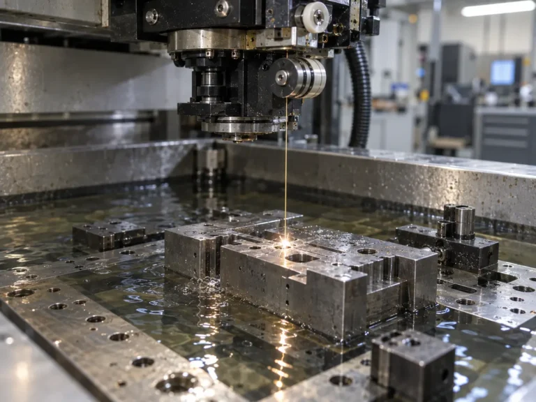
- Wire EDM: Produces accurate profiles and very small corner radii in conductive materials.
- Broaching: Efficient for accurate square holes in medium- or high-volume production.
- Slotting or shaping: Suitable for certain internal square profiles and heavy components.
A perfectly sharp internal corner is difficult or expensive to manufacture. Laser cutting, milling and wire EDM all leave some corner radius, although the achievable radius varies significantly.
The drawing should specify the square width, corner radius, dimensional tolerance, position tolerance, depth and required clearance. If a square shaft has external corner radii that do not match the hole, it may not fully enter the square opening even when the nominal widths are correct.
Quick Comparison
| Hole type | Main geometry | Primary function | Fastener position |
|---|---|---|---|
| Counterbore | Cylindrical recess with flat bottom | Recess a cylindrical screw or bolt head | Flush with or below the surface |
| Countersink | Conical recess | Seat a tapered flat-head screw | Flush with or below the surface |
| Spotface | Very shallow flat-bottomed recess | Create a level bearing surface | Fastener remains exposed |
| Through hole | Passes through the complete part | Clearance, positioning or passage | Depends on the assembly |
| Blind hole | Ends inside the part | Mounting without penetrating the opposite surface | Depends on the assembly |
| Square hole | Square internal profile | Anti-rotation and torque transmission | Inserted component fits inside |
FAQ
Common engineering hole types include through holes, blind holes, counterbores, countersinks, spotfaces, threaded holes, reamed holes, stepped holes, tapered holes and square holes. The correct choice depends on the required fastener, fit, load and manufacturing process.
A counterbore has straight cylindrical walls and a flat bottom for cylindrical screw or bolt heads. A countersink has a conical surface for tapered flat-head screws. They cannot normally be substituted because the fastener-head geometries are different. Counterbore vs. countersink
A spotface is very shallow and only creates a flat bearing surface for a bolt head, nut or washer. A counterbore is deeper and provides enough space to recess the fastener head.
A through hole passes completely through the part, while a blind hole stops at a specified depth inside it. Blind holes require more careful control of depth, chip removal and bottom clearance.
The countersink angle must match the fastener head. A 90° countersink is common for ISO metric screws, while 82° is widely used for Unified inch-series flat-head screws. The applicable fastener drawing or standard should always be checked.
Square holes can be produced by punching, laser cutting, CNC milling, broaching, slotting or wire EDM. The best method depends on material thickness, tolerance, corner radius and production quantity.