1. What Is CNC Milling?
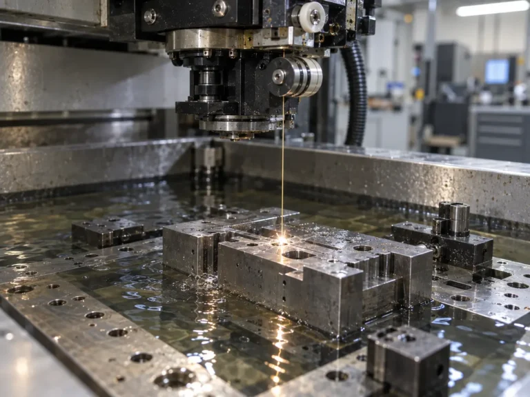
CNC milling (Computer Numerical Control Milling) is a precision machining process that uses computer-controlled cutting tools to remove material from a solid workpiece and create components according to a digital design model.
Unlike forming processes such as stamping, injection molding, or casting, CNC milling is a subtractive manufacturing process. Material is gradually removed through rotating tools until the required geometry, dimensional accuracy, and surface finish are achieved. The typical workflow includes:
3D CAD Model → CAM Programming → CNC Machining → Inspection → Finished Component
Engineers create the part model in CAD software, define machining strategies through CAM software, and generate tool paths that control spindle speed, cutting direction, feed rate, and machining sequence.
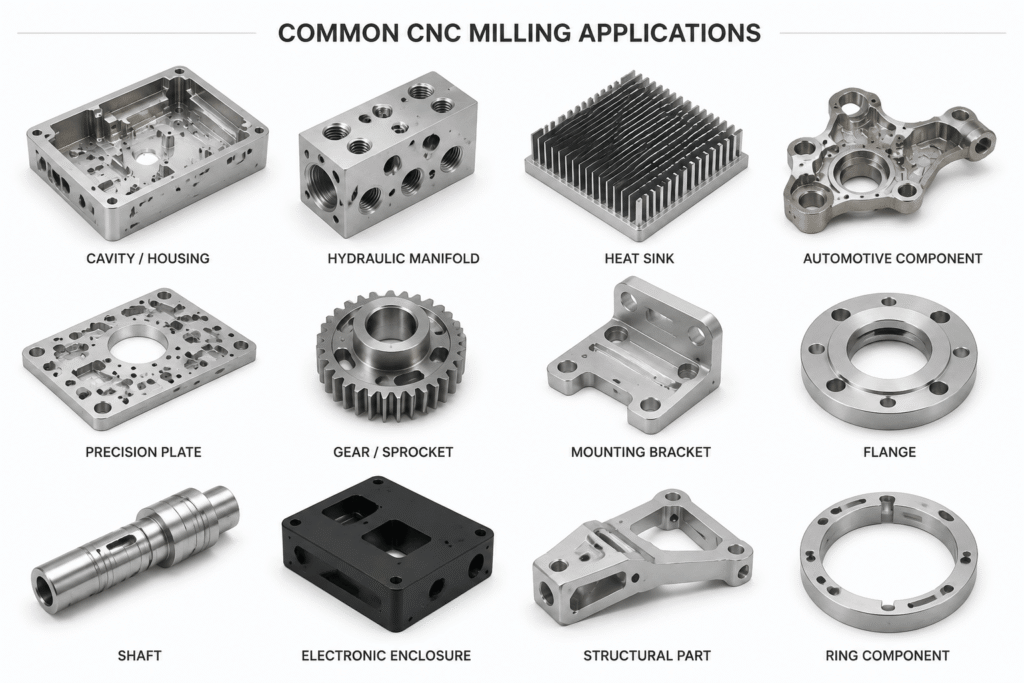
CNC milling is widely used for precision mechanical parts, including automotive components, industrial equipment parts, electronic housings, heat sinks, and automation components.
2. Basic Working Principle of CNC Milling
The core of CNC milling is the controlled movement between the cutting tool and the workpiece.
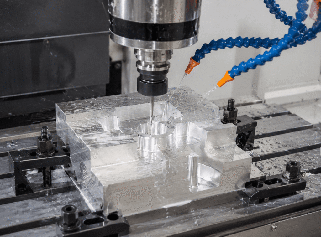
During machining, the spindle rotates the cutting tool at high speed. The cutting edges remove material through controlled contact with the workpiece. The machine controls tool movement through multiple axes:
- X-axis: Horizontal movement
- Y-axis: Longitudinal movement
- Z-axis: Vertical cutting movement
By combining these movements, CNC machines can manufacture complex features such as pockets, slots, holes, mounting surfaces, and curved profiles. For more complex geometries, four-axis and five-axis machining allow the tool to approach the workpiece from different directions, reducing setups and improving accuracy. Most CNC milling operations are divided into three stages:
Rough Machining → Semi-Finish Machining → Finish Machining
Rough machining removes most excess material efficiently, while finishing operations achieve final dimensions, tolerances, and surface requirements.
3. CNC Milling Capabilities and Applications
CNC milling provides high flexibility for manufacturing complex metal components that require precision and structural integrity. Typical applications include:
- Precision mounting surfaces;
- Heat sink bases;
- Mechanical housings;
- Fixture components;
- Automation equipment parts;
- Prototype and low-volume production components.
However, machining performance depends greatly on product design. A component that is difficult to machine may increase cycle time, tool consumption, and manufacturing cost. Therefore, DFM considerations should be included during the design stage.
4. Key CNC Milling DFM Design Guidelines
4.1 Optimize Pocket Depth and Avoid Excessive Deep Cavities
Deep pockets increase machining difficulty because they require longer cutting tools. Longer tools have lower rigidity, making them more likely to produce vibration, poor surface finish, and unstable dimensions. Recommended practices:
- Keep cavity depth-to-width ratio around 3:1 or lower whenever possible
- Avoid narrow pockets requiring long tools;
- Add proper corner radii to improve tool accessibility.
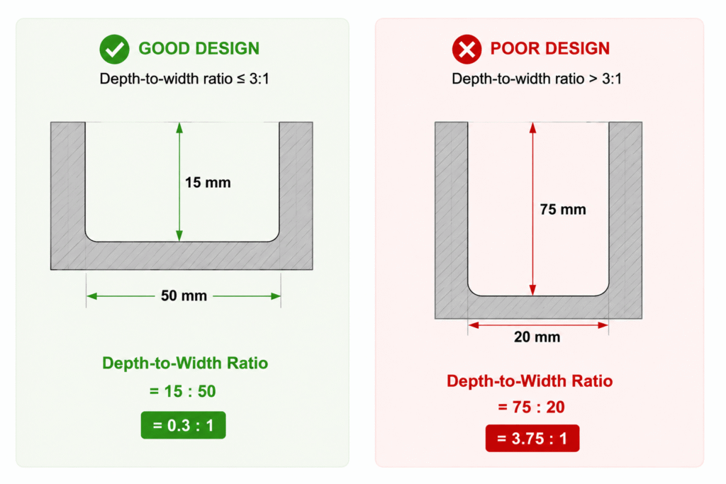
For precision aluminum components, many manufacturers prefer redesigning deep cavities with reinforcement ribs or split structures when machining becomes inefficient.
4.2 Design Internal Corners Based on Tool Geometry
CNC milling tools are rotational, which means they cannot create a true sharp 90° internal corner. Sharp internal corners usually require smaller tools, slower machining speeds, and additional processing time. Recommended design principles:
- General structures: Internal radius ≥ R1mm
- Small precision parts: R0.3–R0.5mm
- Cost-sensitive designs: Use larger corner radii whenever possible
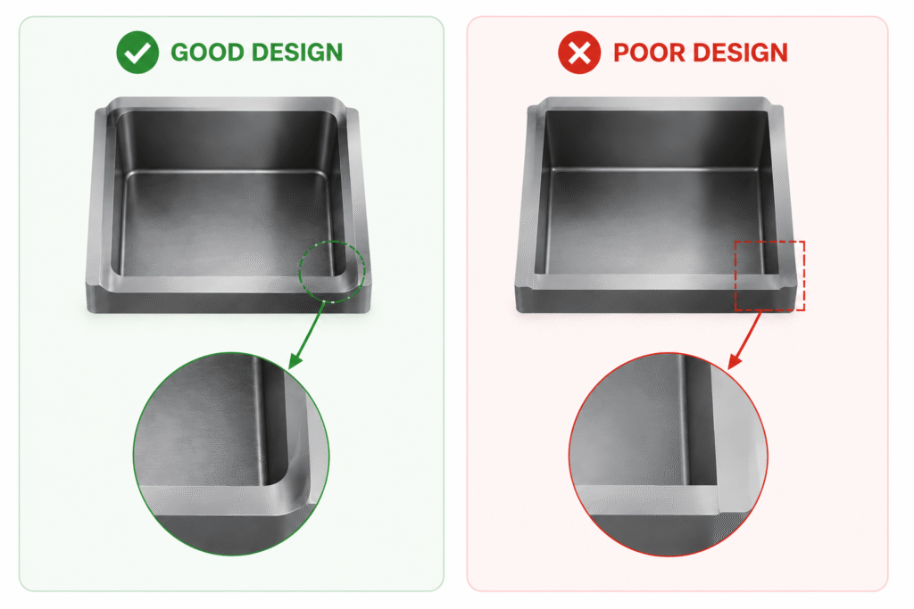
Larger internal radii allow larger cutting tools, improving machining efficiency and reducing tool wear.
4.3 Control Wall Thickness to Prevent Deformation
Thin walls are vulnerable to cutting forces and residual stress during machining. Recommended guidelines:
- Aluminum alloy parts: Wall thickness ≥ 1.2mm
- Stainless steel parts: Wall thickness ≥ 1.5–2mm
- Large thin-wall areas should include ribs or supporting structures
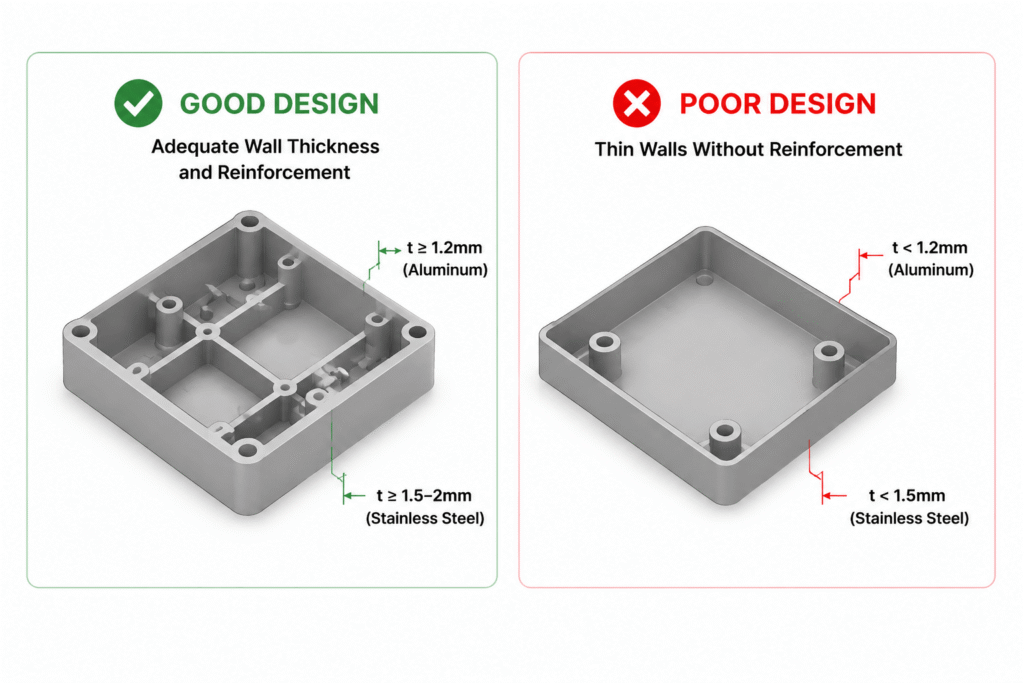
For lightweight components, adding ribs is often more effective than simply increasing material thickness.
44 Minimize Machining Setups
Each additional setup introduces positioning variation and increases labor time. Good DFM practice includes:
- Designing clear machining reference surfaces;
- Reducing unnecessary part repositioning;
- Combining features that can be machined in the same setup.
A well-planned design improves dimensional consistency and production efficiency.
4.5 Apply Functional Tolerances Instead of Excessive Precision
Overly tight tolerances are a common cause of unnecessary machining costs. Typical CNC milling capability:
- General machining: ±0.05mm
- Precision machining: ±0.01–0.02mm
Not every dimension requires high precision. Critical functional features should have strict tolerances, while non-functional dimensions should follow general tolerances.
This approach reduces machining time, inspection requirements, and production risk.
4.6 Optimize Raw Material Utilization
Material utilization is often overlooked during product design but has a direct impact on CNC machining cost, especially for aluminum and stainless steel components.
Many CNC parts are produced from standard stock materials. If the designed thickness does not match available material sizes, manufacturers may need to purchase thicker material and remove excessive material during machining.
For example:
A component designed with a maximum thickness of 10.5mm may require 15mm stock material because 10.5mm is not a standard plate size. Approximately 4.5mm material must then be removed as machining waste.
This creates unnecessary costs:
- Increased raw material waste;
- Longer machining time and higher tool consumption.
Optimizing part dimensions according to available material sizes can significantly improve manufacturing efficiency.
5. CNC Milling Cost Optimization for Purchasing Teams
CNC machining cost is mainly determined by:
Material Cost + Machining Time + Tool Consumption + Fixtures + Surface Treatment + Inspection Requirements
Among these factors, machining time usually has the greatest influence.
Purchasing teams should evaluate not only unit price but also whether the product design is optimized for manufacturing.
Key cost drivers include:
Part Complexity
More pockets, curved surfaces, and machining directions increase programming time and machine hours.
Material Selection
Aluminum alloys generally provide excellent machinability. Stainless steel offers higher strength and corrosion resistance but requires longer machining time.
Production Volume
CNC milling is ideal for prototypes, low-volume production, and precision components. For high-volume production, alternative processes such as stamping, die casting, or injection molding may provide better cost efficiency.
The best manufacturing solution balances performance requirements, production quantity, quality expectations, and total lifecycle cost.
6. Conclusion
CNC milling is more than a machining method; it is a manufacturing process that combines engineering design, material selection, machining technology, and cost management.
For engineers, understanding CNC limitations helps create products that are easier to manufacture and more reliable in production.
For purchasing teams, understanding cost factors helps evaluate suppliers and select the most suitable manufacturing solution.
A successful CNC design does not simply pursue maximum precision or complexity. It achieves the optimal balance between:
Function, Manufacturability, Quality, and Cost.
This is the foundation of modern manufacturing — Design for Manufacturing (DFM).
What is CNC milling used for?
CNC milling is used to manufacture precision mechanical parts, including brackets, housings, heat sinks, tooling components, and complex metal structures.
FAQ
1. What is CNC milling used for?
CNC milling is used to manufacture precision mechanical parts, including brackets, housings, heat sinks, tooling components, and complex metal structures.
2. What is the recommended wall thickness for CNC milling?
For aluminum CNC parts, a wall thickness of approximately 1.2mm or above is commonly recommended to reduce deformation risk.
3. How can CNC machining costs be reduced?
CNC machining costs can be reduced by optimizing part design, minimizing setups, selecting suitable tolerances, and improving raw material utilization.
4. What is DFM in CNC machining?
DFM (Design for Manufacturing) means designing products that are easier, faster, and more economical to manufacture.