1. Understanding Sheet Metal Fabrication
Sheet metal fabrication refers to the process of converting flat metal sheets into functional three-dimensional components through cutting, forming, joining, and finishing operations.
Unlike CNC machining, which creates parts by removing material, sheet metal manufacturing focuses on maximizing material utilization through controlled deformation and structural forming.
Common sheet metal products include: Industrial equipment housings, Electrical control cabinets, Server racks and chassis, Automotive brackets, Battery enclosures, Electronic support structures, Medical equipment frames.
These products usually share common characteristics:
- Relatively uniform sheet thickness
- Structures mainly formed through bending
- High demand for assembly accuracy
- Balance between strength, weight, and cost
1.1 From a Metal Sheet to a Finished Product
A typical sheet metal manufacturing process includes:
Design → Material Preparation → Cutting → Forming → Joining → Finishing
Laser cutting and punching create the initial flat pattern from raw sheet material. CNC bending then transforms the flat sheet into a three-dimensional structure. Welding, riveting, or mechanical fastening combines multiple components into a complete assembly.
2. Sheet Metal Materials and Core Manufacturing Processes
2.1 Common Sheet Metal Materials
| Material | Processability | Corrosion Resistance | Cost Level | Typical Applications |
|---|---|---|---|---|
| Cold Rolled Steel (SPCC) | Excellent | Low, requires surface protection | Low | Chassis, brackets, internal structures |
| Galvanized Steel (SECC/SGCC) | Good | Good | Medium-Low | Server cabinets, electrical enclosures |
| Stainless Steel (SUS) | Good | Excellent | High | Medical equipment, food equipment, appearance parts |
| Aluminum Alloy (AL) | Good | Good | Medium-High | New energy equipment, electronic structures |
2.2 Laser Cutting and CNC Punching
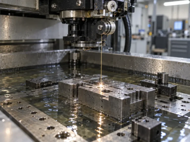
Laser cutting and CNC punching are the two primary methods used for sheet metal blanking. Laser cutting uses a high-energy laser beam to rapidly melt or vaporize metal material along a programmed path, creating accurate contours, holes, and complex profiles.
Compared with traditional cutting methods, laser cutting provides several advantages:
- No dedicated tooling required
- High design flexibility
- Fast response to design changes
- Suitable for prototypes and low-volume production
CNC punching uses mechanical force and tooling to create holes, slots, louvers, and formed features. For high-volume products with repeated hole patterns, CNC punching can provide excellent production efficiency.
2.2.1 Design Considerations for Laser Cutting
During sheet metal design, hole size and geometry should be considered carefully.
A common engineering guideline is: Hole Diameter≥1.5×Sheet Thickness(t).
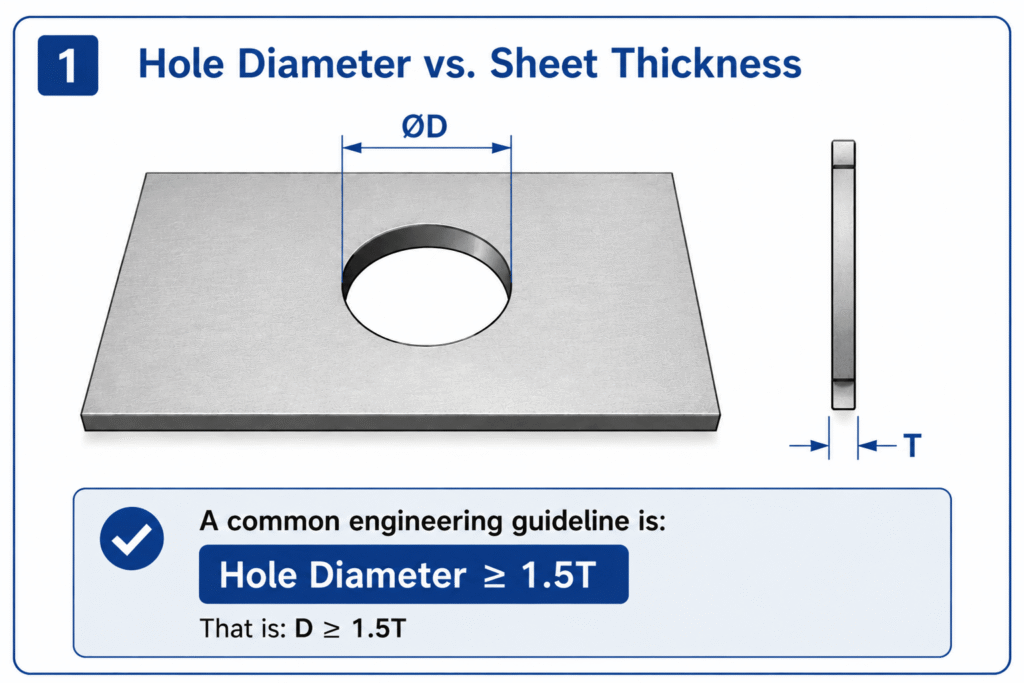
For example, a 1mm thick sheet generally should avoid holes smaller than approximately 1.5mm. Very small holes may result in: Reduced piercing efficiency, Increased processing time, Higher burr risk. Complex sharp corners are also possible with laser cutting, but excessive sharp features increase cutting paths and manufacturing time. Whenever possible, adding reasonable corner radii can improve manufacturing efficiency and stability.
2.3 CNC Sheet Metal Bending
CNC bending is one of the most important forming processes in sheet metal fabrication. The basic principle is: Applying controlled pressure through upper and lower dies to permanently deform metal sheets into the required angles and shapes.
Although bending appears simple, achieving stable accuracy requires consideration of: Material properties, Sheet thickness, Die selection, Bend radius, Spring-back compensation.
2.3.1 Bend Allowance and K-Factor
During bending, the outer surface of the sheet is stretched while the inner surface is compressed. Between these two regions exists a neutral layer where the material length remains relatively unchanged.
The K-factor is used to calculate the correct flat pattern length.
The common formula is:Where:
- BA = Bend allowance
- R = Inside bend radius
- t = Sheet thickness
- K = K-factor
- A = Bend angle
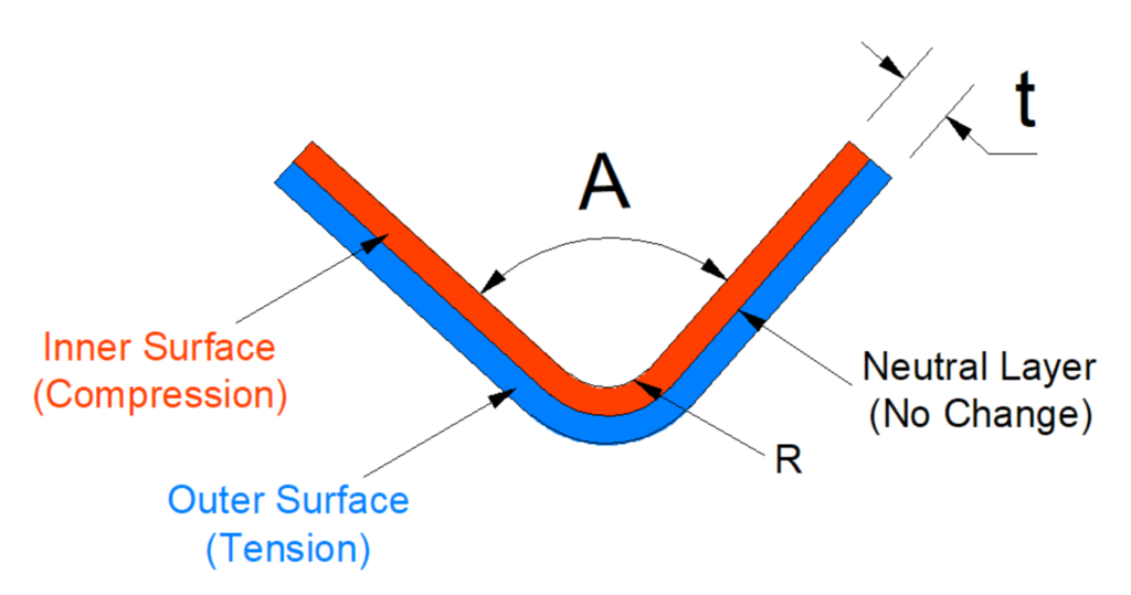
In actual production, the K-factor is not a fixed value. It depends on: Material type, Sheet thickness, Bending method, Tooling condition. Therefore, experienced manufacturers usually establish process databases through actual bending trials.
2.3.2 Bend Radius and Spring Back Control
A common design guideline for sheet metal bending is: R≥t, For example:
| Sheet Thickness | Recommended Bend Radius |
|---|---|
| 1mm | Around R1 |
| 2mm | Around R2 |
| 3mm | Around R3 |
If the bend radius is too small, the material may experience: Surface cracking, Excessive forming force, Reduced part reliability.
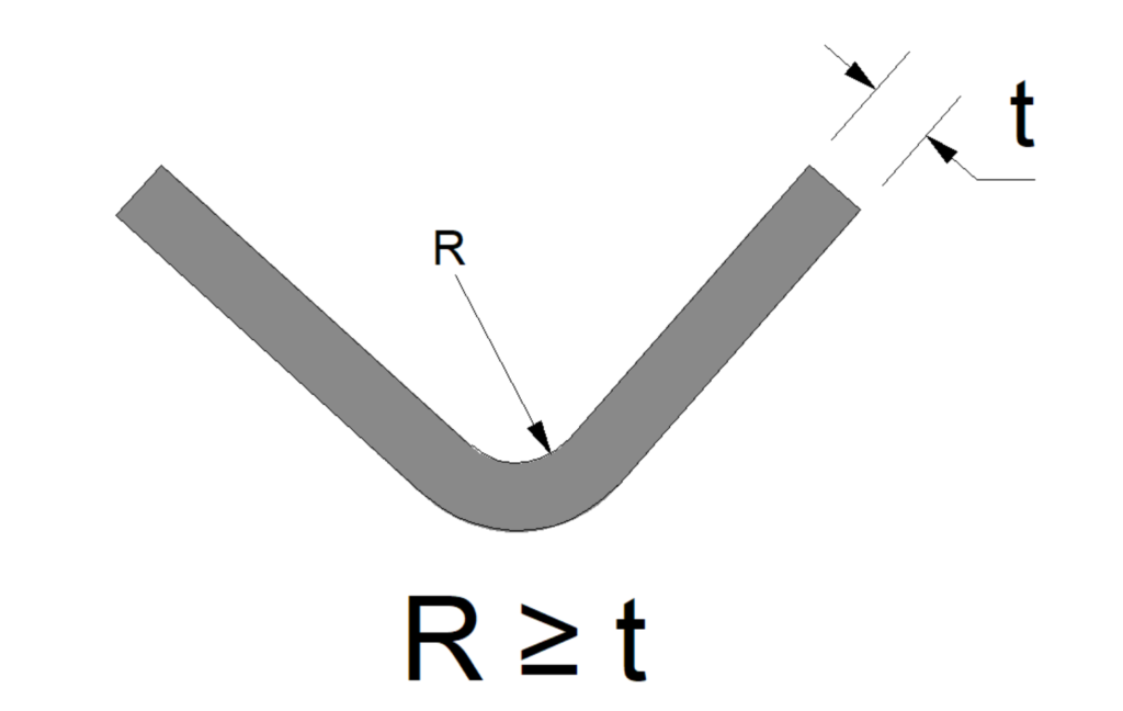
Another important factor is spring back. Because metal has elastic recovery characteristics, the final angle after unloading may differ from the forming angle. For example, A designed 90° bend may return to approximately 91°–93° after forming.
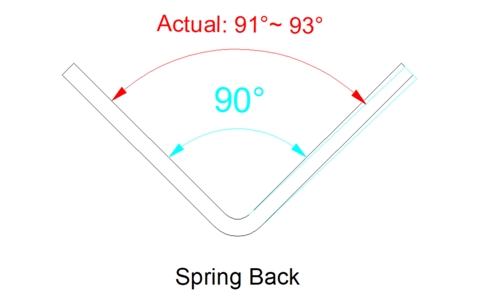
Spring back is influenced by:
| Factor | Influence |
|---|---|
| Material strength | Higher strength causes more spring back |
| Sheet thickness | Thin sheets are more sensitive |
| Bend radius | Larger radius increases spring-back tendency |
| Die clearance | Affects final forming accuracy |
2.4 Welding and Structural Joining
Many sheet metal products are not manufactured from a single bent sheet. Instead, multiple components are combined through welding, riveting, or mechanical fastening to create a complete structure. The selection of joining methods directly affects: 1. Structural strength; 2. Dimensional stability; 3. Appearance quality; 4. Manufacturing efficiency.
Common welding methods used in sheet metal fabrication include TIG welding, MIG welding, resistance spot welding, and laser welding.
| Welding Method | Characteristics | Typical Applications |
|---|---|---|
| TIG Welding | High precision, excellent weld appearance | Stainless steel parts, appearance structures |
| MIG Welding | High efficiency, suitable for production | Steel frames, equipment structures |
| Spot Welding | Fast and consistent | High-volume sheet metal assemblies |
| Laser Welding | Low heat input, minimal deformation | Precision sheet metal components |
2.4.1 Welding Deformation Control
One of the most important challenges in sheet metal welding is deformation. During welding, localized heating causes thermal expansion, and subsequent cooling creates shrinkage stress. These internal stresses may result in: Warpage, Dimensional distortion, Flatness problems, Misalignment during assembly. The main factors affecting welding deformation include:
| Factor | Influence |
|---|---|
| Sheet thickness | Thin sheets are more sensitive to deformation |
| Weld length | Longer welds create greater shrinkage |
| Heat input | Higher heat increases deformation risk |
| Welding sequence | Improper sequence increases residual stress |
In practical manufacturing, deformation is controlled through optimized welding sequences, proper fixture design, balanced welding methods, and controlled heat input. For example, instead of continuously welding one side of a structure, manufacturers often use: Symmetrical welding, Intermittent welding, Skip welding to balance thermal stress.
2.5 Deburring, Tapping, Riveting and Post-processing
After cutting and forming operations, sheet metal parts usually require additional processes to meet assembly and functional requirements.
2.5.1 Deburring
Laser cutting, punching, and forming processes may generate: Sharp edges, Burrs, Cutting residue. If these defects are not removed, they may affect: Assembly accuracy, Operator safety, Surface finishing quality. Common deburring methods include:
| Method | Characteristics |
|---|---|
| Manual grinding | Flexible, suitable for low-volume production |
| Barrel finishing | Efficient for batch processing |
| Automatic deburring | High consistency and repeatability |
2.5.2 Tapping and Threaded Features
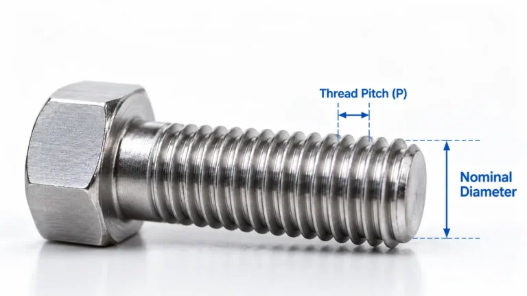
Many sheet metal components require threaded holes for assembly. Typical applications include: Screws, Fasteners, Brackets, Electronic assemblies. However, directly tapping thin sheet metal may result in insufficient thread engagement and reduced fastening strength. For thin sheet applications, manufacturers often use: Self-clinching nuts, Rivet nuts, Weld nuts to improve connection reliability.
During design, engineers should consider: Sheet thickness, Edge distance, Installation space, Load direction. Improper placement may cause: Sheet deformation, Loose fasteners, Assembly interference.
2.5.3 Riveting and Self-clinching Components
Self-clinching technology is widely used in sheet metal manufacturing because it provides strong mechanical fastening without welding. Common components include: Clinching nuts, Clinching studs, Standoffs. Advantages include: No heat deformation, Fast installation, Good repeatability, Suitable for mass production.
However, proper design is required. Factors such as sheet thickness, hole size, edge distance, and installation direction must match the specifications of the fastening components.
2.6 Surface Treatment Selection
After mechanical fabrication, sheet metal parts often require surface treatment depending on environmental conditions, appearance requirements, corrosion protection levels, and cost targets. Common surface treatment processes include:
| Process | Main Purpose |
|---|---|
| Powder Coating | Corrosion protection and appearance improvement |
| Liquid Painting | Flexible appearance and color options |
| Electroplating | Corrosion protection and functional performance |
| Anodizing | Surface enhancement for aluminum parts |
3. Sheet Metal Design for Manufacturing (DFM) Guidelines
3.1 Design For Manufacturing
A successful sheet metal design must not only satisfy product functions but also consider manufacturing feasibility.
DFM (Design For Manufacturing) means optimizing product design before production begins, ensuring that the part can be manufactured efficiently, consistently, and economically. Many manufacturing problems are not caused by insufficient equipment capability, but by design decisions made without considering manufacturing limitations.
Typical examples include:
- Holes located too close to bending areas
- Missing relief features
- Excessively tight tolerances
- Overly complex welding structures
- Difficult assembly requirements
A good sheet metal design minimizes these issues before production starts.
3.2 Bend Area Design and Material Relief
Bending is one of the processes most likely to affect dimensional accuracy.
During bending, the material experiences both tension and compression. Therefore, sufficient space must be provided around bending areas to allow controlled material flow.
One common design issue is placing holes too close to bend lines.
When a hole is too close to a bend area, deformation during bending may cause: Hole distortion, Position deviation, Assembly problems. A common engineering guideline is: L≥2t+R, Where:
- L = Distance from hole center to bend line
- t = Sheet thickness
- R = Bend radius
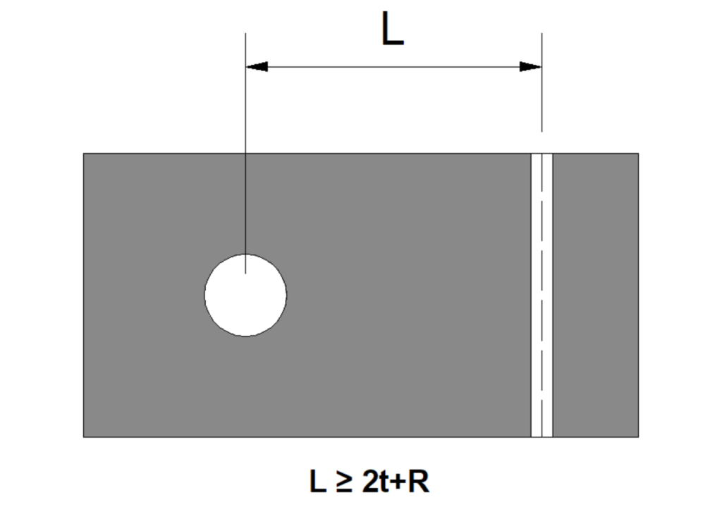
For example, for a 1mm sheet with R1 bending, the hole should generally maintain approximately 3mm or more distance from the bend region. The actual value should still be verified based on material properties and manufacturing conditions.
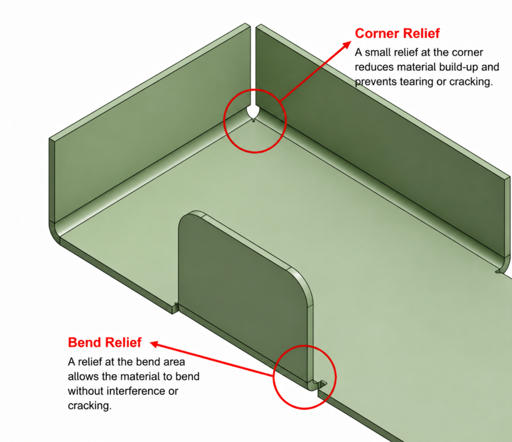
3.3 Bend Relief and Avoiding Interference
When multiple bends meet, insufficient material clearance may cause: Corner deformation, Cracking, Folding interference. For example, in a U-shaped sheet metal component, if two side walls are bent without proper relief at the corner area, excessive material compression may occur.
Adding appropriate bend relief features helps: Reduce forming stress, Improve dimensional consistency, Prevent tearing. Common relief designs include: Rectangular relief slots, Rounded relief slots, Clearance cutouts.
3.4 Bend Radius Selection
One common mistake in sheet metal design is pursuing extremely sharp corners.
Although sharp bends may appear visually attractive, excessively small bend radii create high tensile stress on the outer surface and increase the risk of cracking.
A general design guideline is: R≥t, However, the actual requirement depends on material characteristics. For example:
- Mild steel generally has good formability;
- Stainless steel usually requires more consideration due to higher strength and spring back;
- Certain aluminum alloys may crack under aggressive bending conditions.
Therefore, bend radius should always be selected based on both material behavior and manufacturing capability.
3.5 Tolerance Design and Manufacturing Capability
Unlike precision machining parts, sheet metal components are affected by multiple variables:
- Material thickness variation
- Cutting accuracy
- Bend spring back
- Welding distortion
- Measurement methods
Therefore, tolerance requirements should be realistic and aligned with manufacturing capability. Typical ranges:
| Part Type | Common Dimensional Capability |
|---|---|
| Standard sheet metal parts | ±0.2~0.5mm |
| Precision sheet metal parts | ±0.1~0.2mm |
| Special high-precision requirements | Require process validation |
Applying unnecessarily tight tolerances can significantly increase: Processing cost, Inspection workload, Scrap risk. A better approach is to identify critical dimensions that affect function and assembly, while maintaining reasonable tolerances for non-critical features.
3.6 Welding Structure Optimization
Welding design requires a balance between structural strength, manufacturing efficiency, and deformation control.
A common design mistake is excessive welding. For example, requiring continuous full welding on a structure that only needs local reinforcement may not significantly improve product performance, but it will increase: Welding time, Heat distortion risk, Grinding requirements, Manufacturing cost. A better approach is to select the appropriate welding method according to actual loading conditions. Depending on the application, manufacturers may use: Local welding, Intermittent welding, Spot welding, Reinforcement structures, rather than applying unnecessary welds everywhere.
The position and sequence of welds should also be considered during design. Poor welding arrangement may create uneven thermal stress and cause dimensional instability after cooling.
For precision sheet metal assemblies, welding fixtures are often used to control part position and maintain repeatability during production.
3.7 Assembly-Friendly Sheet Metal Design
Sheet metal components are usually not final products by themselves. They are often assembled with other parts, including: Fasteners, Electronic components, Plastic parts, Mechanical assemblies. Therefore, good sheet metal design should consider the assembly process from the beginning. Important factors include: Accessibility for tools, Screw installation space, Positioning references, Assembly sequence, Error-proof design.
A design that is easy to manufacture but difficult to assemble may still create unnecessary production costs. For mass production, assembly efficiency becomes increasingly important. Features such as locating holes, positioning tabs, and standardized fastening methods can significantly improve assembly consistency.
4. Sheet Metal Manufacturing Cost Analysis
4.1 Sheet Metal Cost Control
The cost of a sheet metal component is not determined only by material weight. A complete sheet metal quotation usually includes multiple cost elements throughout the manufacturing process:
| Cost Element | Main Influencing Factors |
|---|---|
| Material Cost | Material type, thickness, utilization rate |
| Cutting Cost | Cutting length, hole quantity, processing time |
| Bending Cost | Number of bends, tooling changes |
| Welding Cost | Weld length, labor time, fixture requirements |
| Secondary Operations | Deburring, tapping, riveting |
| Surface Treatment | Process type, color, quantity |
| Tooling Cost | Dies, fixtures, inspection tools |
Among these factors, material cost is usually the basic component, but manufacturing complexity often determines the final price difference.
4.2 Features That Commonly Increase Sheet Metal Cost
Complex geometries are one of the major cost drivers. For example, a large number of small holes may appear insignificant from a material removal perspective, but each hole requires additional machine movement, positioning, and processing time. Similarly, excessive bending operations increase manufacturing complexity. Each additional bend introduces:
- More machine operations
- Additional setup time
- Greater dimensional variation
Whenever possible, designers should simplify unnecessary features while maintaining product functionality.
4.3 The Impact of Tight Tolerances
Tolerance requirements have a direct relationship with manufacturing cost. For example: A standard sheet metal component may normally be produced within ±0.2mm. If the drawing requires ±0.05mm, additional controls may be necessary: Special fixtures, More accurate process parameters, Increased inspection frequency.
If a part requires complete dimensional inspection reports or 100% inspection, additional quality costs will also be introduced. A practical engineering approach is to apply tighter tolerances only to functional areas that affect: Assembly, Performance, Safety, while maintaining reasonable tolerances for non-critical features.
5. Sheet Metal Fabrication vs Metal Stamping
Sheet metal fabrication focuses on flexibility and process combination, while metal stamping focuses on high-speed, high-volume production using dedicated tooling. Neither process is universally better. The appropriate choice depends on product structure, production volume, cost objectives, and product lifecycle.
Production quantity is one of the most important factors when selecting a manufacturing process.
| Production Volume | Recommended Approach |
|---|---|
| Prototype / Low Volume | Sheet Metal Fabrication |
| Medium Volume | Evaluate based on structure and cost |
| High Volume Production | Metal Stamping |
For a newly developed product with uncertain market demand, sheet metal fabrication reduces initial investment risk. For mature products requiring hundreds of thousands or millions of pieces, stamping usually provides better unit cost performance.
In modern manufacturing, sheet metal fabrication and stamping are often complementary rather than competing technologies.
FAQ
1. What is sheet metal fabrication?
Sheet metal fabrication is the process of cutting, bending, forming, and assembling metal sheets into custom precision parts.
2. What materials can be used for sheet metal fabrication?
Common materials include stainless steel, aluminum, galvanized steel, cold-rolled steel, copper, and brass.
3. What sheet metal fabrication processes do you provide?
We provide laser cutting, CNC bending, stamping, welding, riveting, tapping, surface finishing, and assembly services.
4. What tolerances can be achieved in sheet metal fabrication?
Typical sheet metal tolerances range from ±0.1 mm to ±0.3 mm depending on material, design complexity, and manufacturing process.
5. What information is required for a sheet metal fabrication quote?
A quotation usually requires 2D drawings, 3D models, material specifications, surface finish requirements, and production quantities.
6. Can you provide custom sheet metal fabrication for prototypes and mass production?
Yes, we support custom sheet metal prototyping, low-volume production, and high-volume manufacturing.