1. What is CNC Turning?
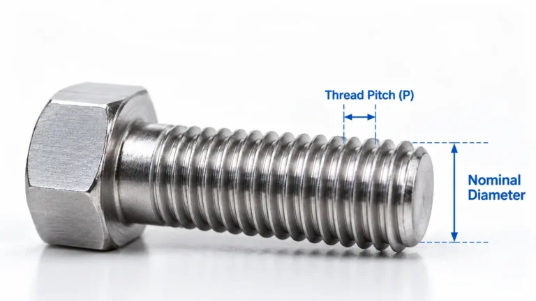
CNC Turning (Computer Numerical Control Turning) is a precision machining process in which the workpiece rotates while stationary cutting tools remove material under CNC control. The process is primarily used to manufacture cylindrical or rotational parts, including shafts, bushings, threaded components, valve bodies, fittings, connectors and other high-precision mechanical parts. Compared with conventional turning, CNC Turning delivers higher dimensional consistency, better repeatability and significantly improved production efficiency.
The process is widely adopted across the automotive, aerospace, medical device, industrial automation, electronics and energy industries because it offers stable quality for both prototype development and high-volume manufacturing. As a result, Custom CNC Turned Parts have become one of the most common precision components in modern mechanical products.
2. CNC Turning Working Principle and Standard Manufacturing Process
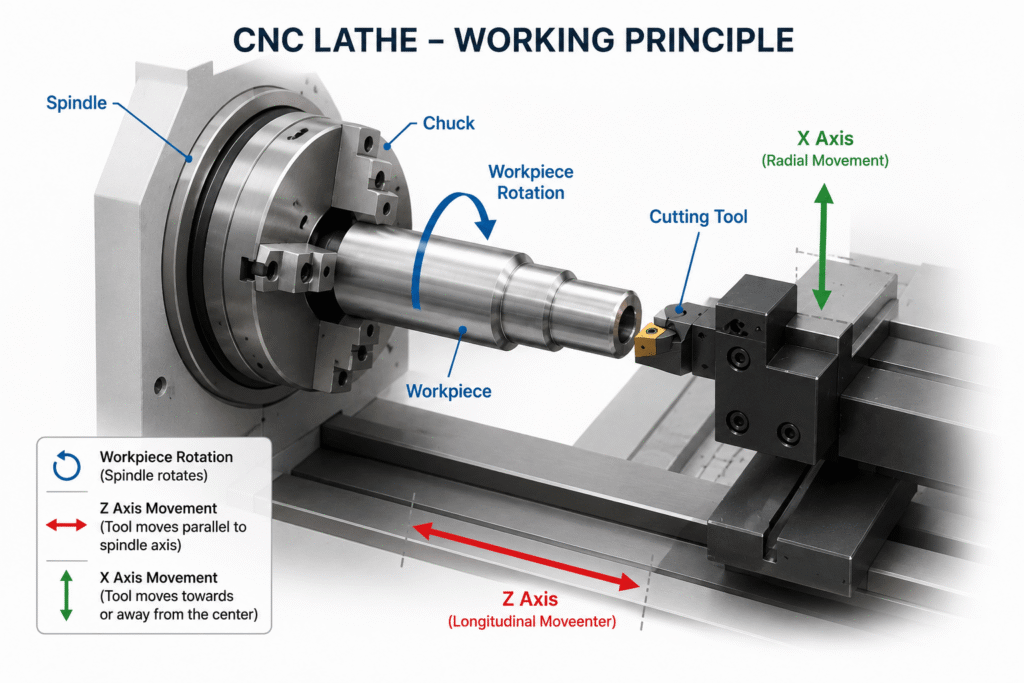
During CNC Turning, the spindle rotates the workpiece while cutting tools move along programmed X- and Z-axis paths to remove material. Cutting speed, feed rate, depth of cut and tool compensation are continuously controlled by the CNC system to achieve the required dimensional accuracy, surface finish and geometric tolerances.
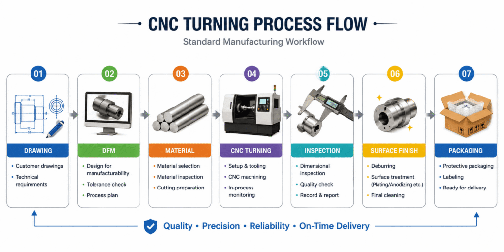
A standard CNC Turning Service generally follows a controlled manufacturing workflow consisting of drawing review, DFM evaluation, raw material verification, fixture setup, rough machining, semi-finishing, finish machining, in-process inspection, deburring, cleaning, final inspection and packaging. For production programs, most international manufacturers require First Article Inspection (FAI) approval before mass production and apply Statistical Process Control (SPC) to monitor critical dimensions throughout manufacturing.
Typical machining capabilities vary depending on equipment, materials and part geometry, but the following values are commonly accepted within the precision machining industry.
| Item | Typical Industry Capability |
|---|---|
| General Tolerance | ±0.01 mm |
| High Precision Tolerance | ±0.005 mm |
| Roundness | ≤0.005 mm |
| Concentricity | ≤0.01 mm |
| Surface Finish | Ra 3.2–0.8 μm (Ra 0.4 μm achievable) |
| Minimum Diameter | Approximately Ø0.5 mm |
| Maximum Diameter | Over Ø500 mm (machine dependent) |
Common materials include stainless steel (303, 304, 316), carbon steel, alloy steel, aluminum alloys (6061, 7075), brass, copper, titanium alloys and engineering plastics such as POM, PEEK and Nylon. Cutting parameters, insert geometry and coolant strategy should always be selected according to material characteristics to maximize tool life and machining stability.
3. Design for CNC Turning: Common Problems and Industry-Proven Improvements
Many machining issues originate from the product design rather than the manufacturing process. Applying Design for Manufacturability (DFM) principles during product development can reduce machining time, improve quality consistency and lower production costs.
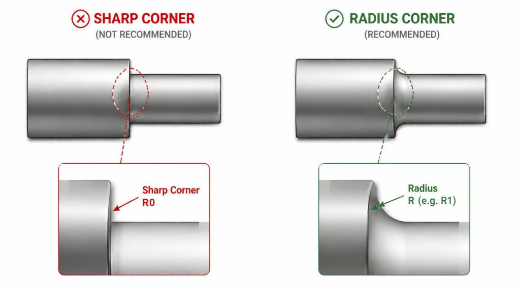
3.1 Problem: Sharp internal corners cannot be fully machined.
Standard turning inserts always have a nose radius, making perfectly sharp internal corners impossible. The recommended solution is to design internal radii of at least R0.5–R1.0 mm or larger than the insert nose radius. This improves tool accessibility, reduces insert wear and produces a more stable surface finish.
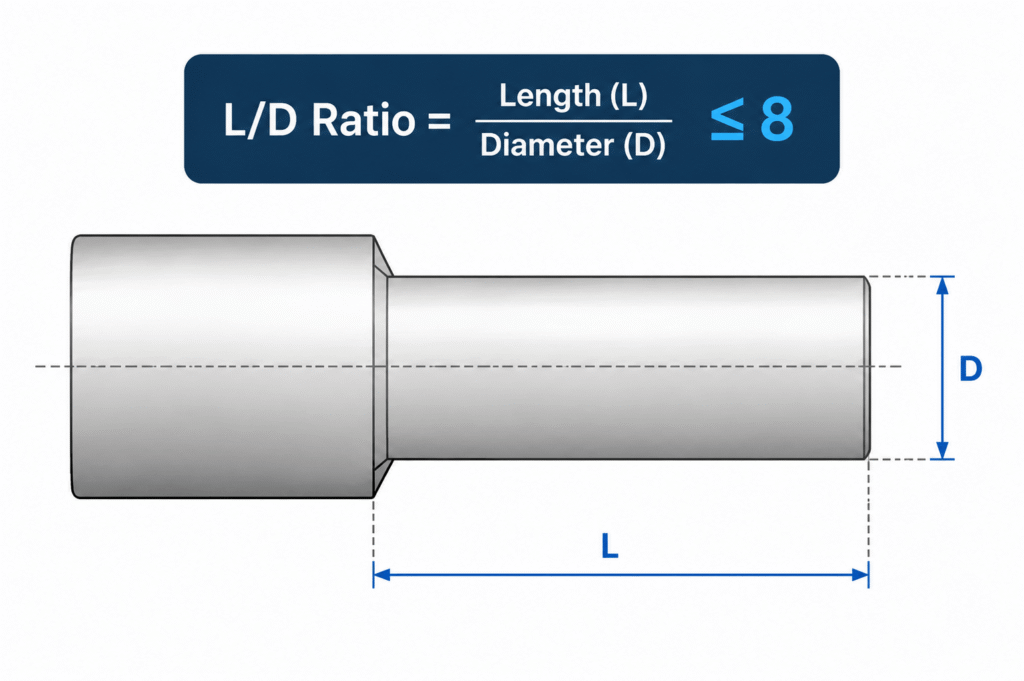
3.2 Problem: Long and slender shafts vibrate during machining.
When the length-to-diameter ratio becomes excessive, workpiece deflection affects roundness and concentricity. Industry practice recommends keeping the ratio below approximately 8:1 whenever possible. For unavoidable long shafts, engineers should reserve support locations for tailstocks or steady rests and increase clamping rigidity to minimize vibration.
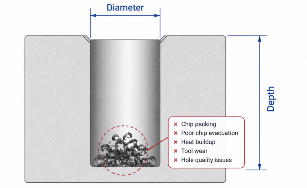
3.3 Problem: Deep holes create chip evacuation difficulties.
Blind holes with excessive depth often trap chips, resulting in poor surface quality, dimensional instability and premature tool failure. A depth-to-diameter ratio below 5:1 is generally preferred. If deeper holes are required, chip-breaking geometries, high-pressure coolant systems and staged drilling strategies should be incorporated into both product design and machining process planning.
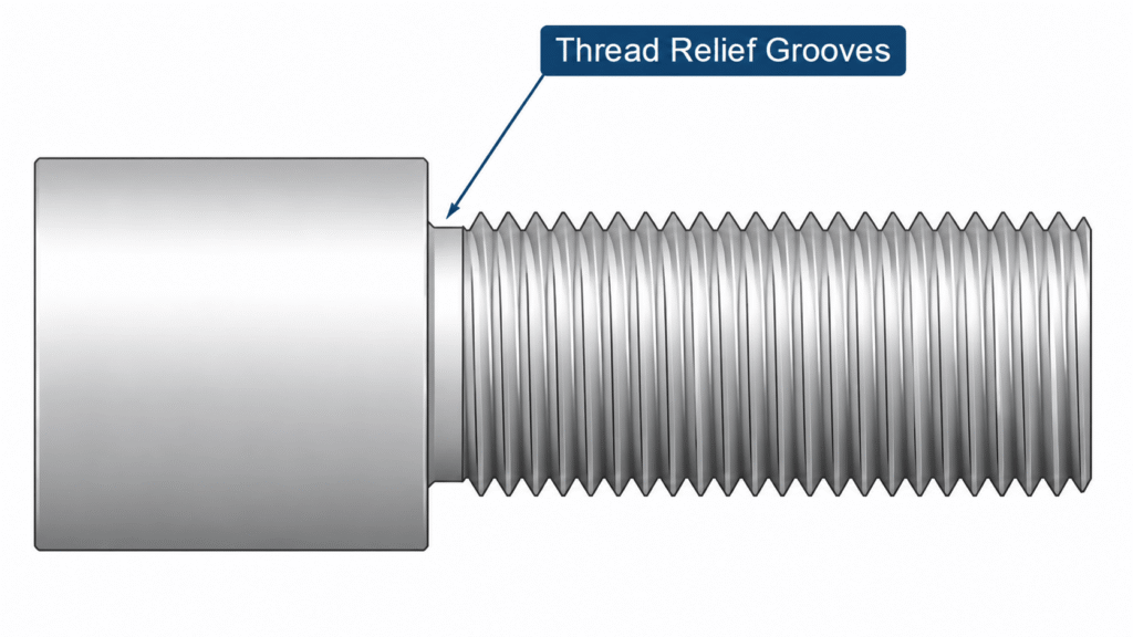
3.4 Problem: Threads terminate directly against shoulders.
Threads positioned immediately adjacent to shoulders prevent proper tool withdrawal and frequently produce incomplete thread profiles. Adding standardized thread relief grooves according to ISO thread machining practice provides sufficient tool clearance, improves thread quality and reduces rework during inspection.
These engineering improvements are widely adopted by automotive, aerospace and medical manufacturers because they shorten machining cycles, improve process capability and reduce manufacturing costs without affecting product functionality.
4. How to Choose a Reliable CNC Turning Supplier
Choosing a reliable CNC Turning Manufacturer is about more than obtaining the lowest quotation. Buyers should evaluate whether the supplier has the machining capability required for the project, including the ability to achieve specified tolerances, process the required materials, support prototype and volume production, and provide complete secondary operations such as milling, threading, surface finishing and assembly. A supplier with integrated manufacturing capabilities can simplify the supply chain, reduce lead times and improve overall project efficiency.
Quality assurance and engineering support are equally important. A professional CNC Turning Service provider should operate under recognized quality systems such as ISO 9001 or IATF 16949, perform First Article Inspection (FAI), and provide inspection reports, material certificates and full product traceability when required. Suppliers that perform DFM analysis before production can also identify potential machining risks, optimize part designs and reduce unnecessary manufacturing costs, resulting in more consistent quality and faster product development.
FAQ
1. Is CNC Turning the same as CNC Lathe Machining?
Yes. CNC Turning and CNC Lathe Machining are different names for the same machining process. Both use a CNC lathe to produce precision cylindrical and rotational parts.
2. What is the difference between CNC Turning and CNC Milling?
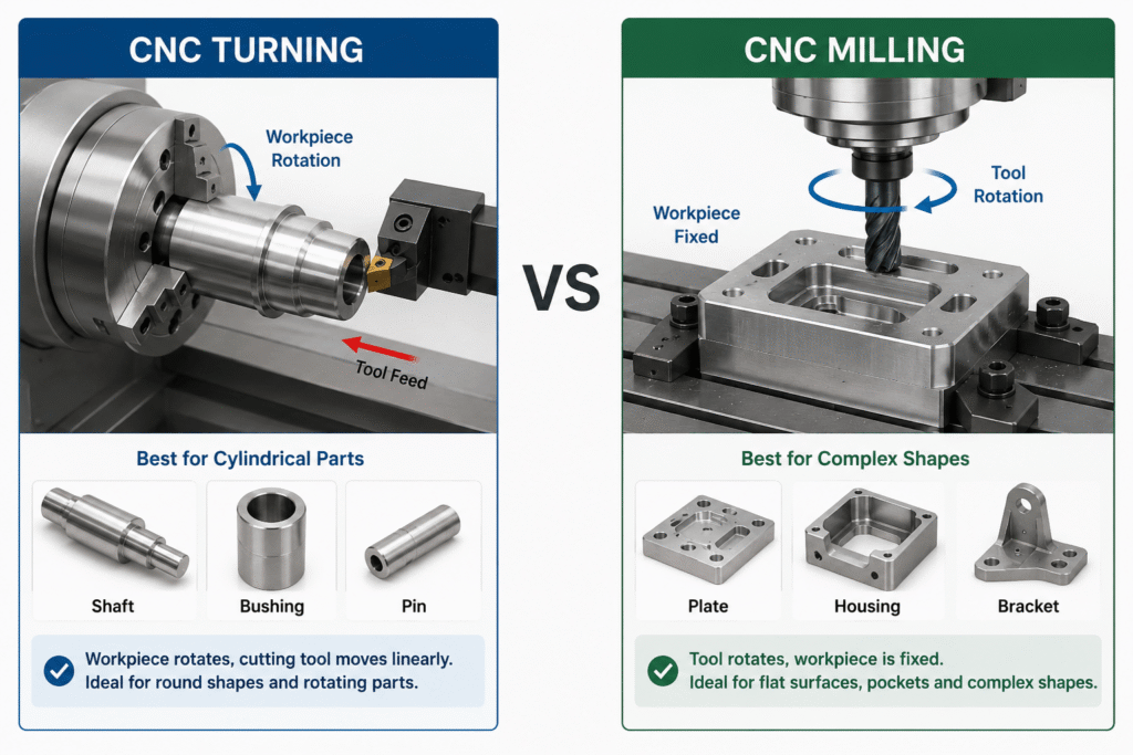
CNC Turning rotates the workpiece, while CNC Milling rotates the cutting tool. Turning is best for round parts, while milling is better for flat or complex shapes.
3. What machining tolerance can CNC Turning achieve?
Most CNC Turning parts are produced to ±0.01 mm, while high-precision applications can achieve ±0.005 mm or better with the right equipment and process.
4. Which materials are suitable for CNC Turning?
CNC Turning can machine stainless steel, aluminum, brass, copper, carbon steel, titanium and many engineering plastics. The material is selected based on the part’s strength, weight and application.
5. Why do CNC turned parts produce burrs?
Burrs are usually caused by tool wear or improper cutting parameters. Using sharp tools and optimized machining settings helps minimize burr formation.
6. What factors affect CNC Turning costs?
Material, machining time, tolerances, part complexity and production quantity are the main cost factors. A machining-friendly design can significantly reduce manufacturing costs.
7. How can I design parts for better CNC Turning performance?
Avoid overly deep holes, long slender shafts and unnecessary tight tolerances whenever possible. Simple design improvements can reduce machining time, improve quality and lower costs.