1. Key Project Controls
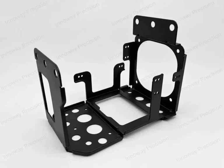
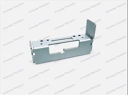
This precision metal stamping case study shows how Innoway Precision controlled hole alignment after bending a galvanized steel component for printing equipment. The alignment between the round hole and the profiled opening was critical to assembly.
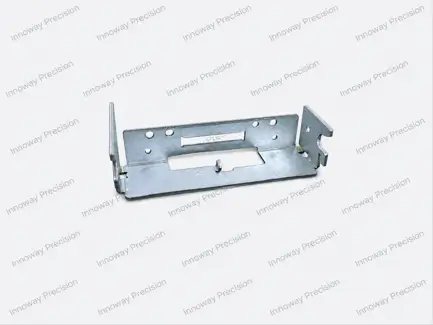
| Control Item | Requirement / Solution |
|---|---|
| Material | 1.2 mm galvanized steel |
| Critical Feature | Concentricity between the round hole and the profiled opening on opposite sides of the part after bending |
| Concentricity Requirement | 0.05 mm |
| Threaded Holes | 4 × M2 per part |
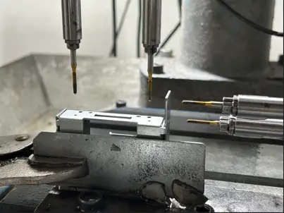
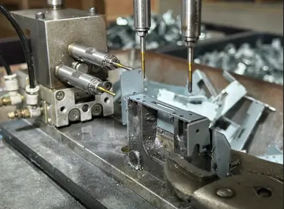
| Tapping Method | Custom multi-spindle station that taps all four holes simultaneously |
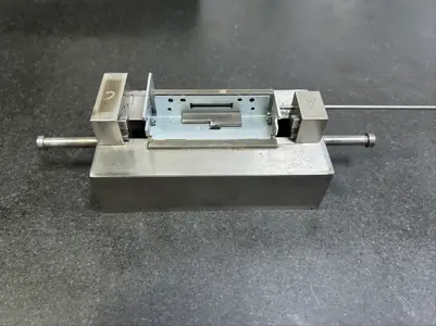
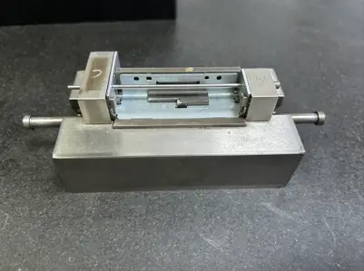
| Quality Control | 100% inspection using a dedicated checking fixture |
| Inspection Coverage | Three critical dimensions checked on every part |
2. Controlling Hole Alignment After Bending
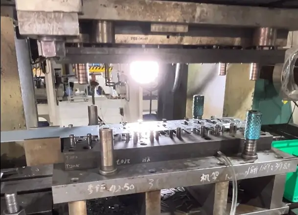
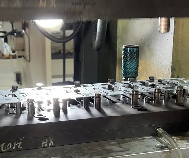
Bending and springback can shift the openings relative to each other even when each opening meets its size specification. We designed the stamping tooling around a common datum for punching, locating, and forming to control their alignment after bending.
3. Tapping Four M2 Holes in One Setup
The multi-spindle station completes all four threads in a single clamping cycle, reducing handling and the risk of missed threads.
4. Inspecting Every Part Before Packing
The dedicated fixture checks the customer’s 0.05 mm concentricity requirement as part of the inspection before packing. This helps catch alignment issues before the parts reach the customer’s assembly line.
5. From Tooling Design to Assembly Fit
For this printer bracket, assembly depended on how the round hole and the profiled opening lined up after bending. A common datum helped control that relationship during stamping and forming, and a dedicated fixture checked the customer’s 0.05 mm concentricity requirement on every part before packing.
For similar stamped parts, agree on which features must align in the formed part, how the part will be located for inspection, and how acceptance will be checked before the tooling design is finalized.