Understanding Material Strength and Stress
A material described as “strong” can still fail in the wrong application. The useful question is how the load acts on the part—and which material property matches that load.
Strength is expressed as stress: force per unit area, commonly in megapascals (MPa). 1 MPa equals 1 N/mm². For a uniformly loaded section, dividing force by the relevant area gives average stress; local peaks near holes or corners can be higher.
1. Compressive Strength: Resistance to Squeezing
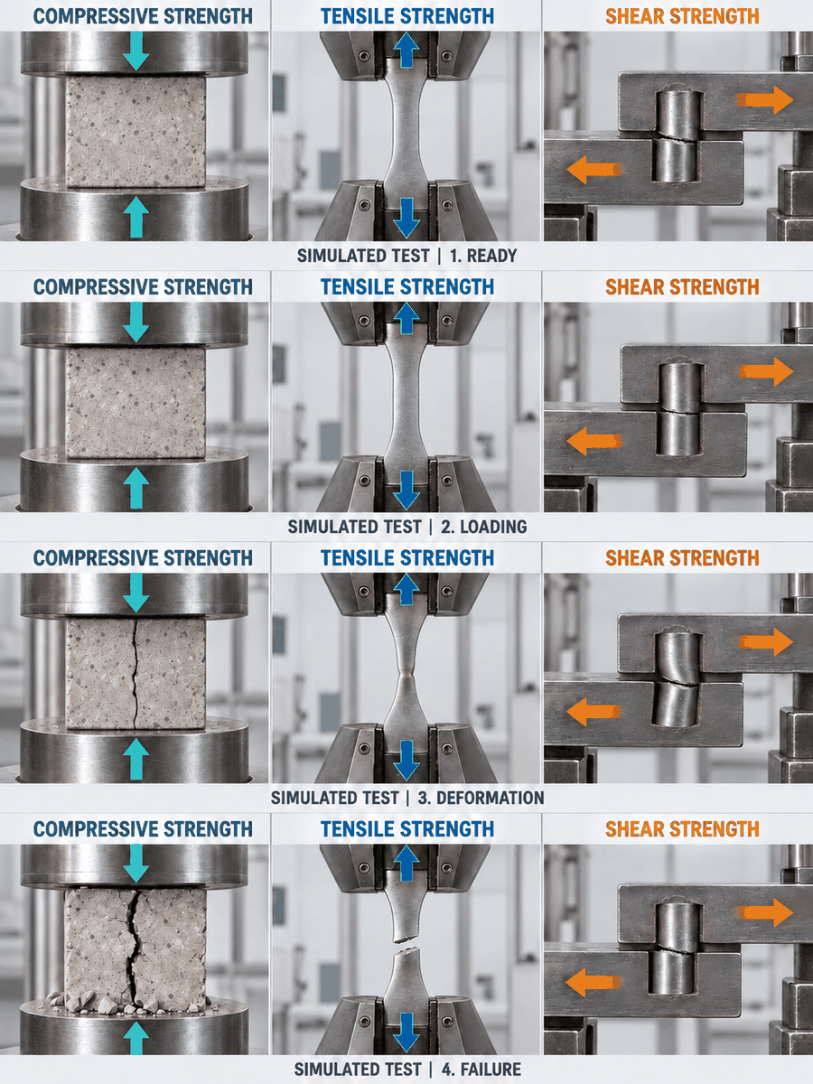
Compressive strength is the maximum compressive stress a material sustains before failure under a specified test. Opposing forces push inward, tending to shorten the specimen.
Concrete, brick and ceramic components can crush, split or develop inclined cracks when overloaded. Ductile metals—metals capable of substantial permanent deformation—may instead flatten and bulge without a distinct breaking point. Their reports may therefore specify compressive yield strength or stress at a stated deformation rather than an ultimate value. Compression testing reference
Where it matters: masonry bearing blocks, concrete pedestals and short spacers supporting equipment.
2. Tensile Strength: Resistance to Pulling
Tensile strength, usually meaning ultimate tensile strength (UTS), is the highest engineering stress reached during a pulling test. It equals the maximum tensile force divided by the specimen’s original cross-sectional area; it is not necessarily the stress at final fracture. Tensile strength reference
Many ductile metals stretch and then develop a locally narrowed region, called a neck, before breaking. Brittle materials can fracture with little visible stretching.
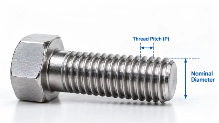
Where it matters: tie rods, suspension wires and bolts loaded along their length.
3. Shear Strength: Resistance to Sliding Failure
Shear strength is the maximum shear stress a material sustains before rupture. The load acts parallel to the section being assessed, tending to slide one part past the adjacent part. Shear strength reference
A locating pin joining two sideways-loaded plates can be cut across its section. In an adhesive joint, failure may occur within the adhesive or at its interface with the bonded surface, so the joint result also depends on surface preparation and geometry.
Where it matters: riveted connections, shaft keys and bonded lap joints. Scissors provide an everyday example of deliberately causing this type of failure.
FAQ
No. The relationship depends on the material and its direction of loading. Concrete is much weaker in tension, which is why reinforcement is used where significant tensile loads are expected. That relationship is not a universal rule for other materials.
Yield strength identifies the onset of significant permanent deformation, often using a specified offset such as 0.2%. It is usually the more relevant limit when a metal component must retain its shape.
There is no universal conversion. Engineering models can relate tensile and shear yielding for particular material behavior, but those relationships do not establish ultimate shear strength. Use applicable test data or validated design rules.
No. Buckling is a loss of structural stability: a slender member can bow sideways before the material reaches its crushing limit. Length, cross-sectional shape, stiffness and end restraints affect the result.
Laboratories use grips, compression platens or shear fixtures suited to the test. The standard must match the material: ASTM E8/E8M covers metallic tensile testing, while ASTM D732 addresses punching shear of plastics. Compare results only with compatible methods and conditions.
The property governing the part’s likely failure matters most. Real components may experience several stresses together, so assess the complete load case, service conditions and required design margin instead of selecting the largest number on a datasheet.