1. What Is Punch Pin?
A punch pin is one of the key working components in a stamping die. During the press stroke, the punch enters the sheet material and works together with the die opening to shear the material and form round holes, obround holes, slots, or other cut features.
Although a punch pin looks simple, it repeatedly experiences cutting force, impact load, stripping force, and sometimes lateral loading. Small-diameter punches are especially sensitive to bending, edge chipping, fatigue, and breakage in high-speed or progressive stamping. For this reason, punch life depends not only on material hardness, but also on punch geometry, unsupported length, guidance, die clearance, heat treatment, and surface coating.
2. Common Types of Punch Pins
2.1 A-Type Punch
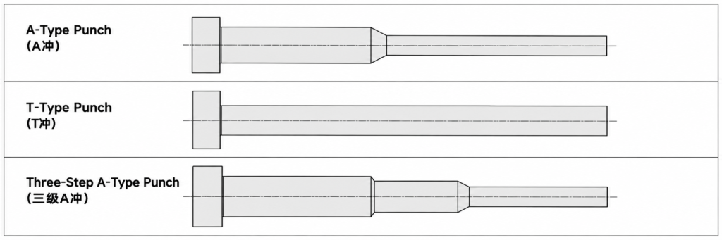
The A-type punch is one of the most common punch structures used in stamping dies. It normally has a larger shank or supporting section and a smaller working diameter near the cutting end.
This stepped structure keeps the main body relatively rigid while limiting the small diameter to the area that actually enters the sheet and die opening. It is widely used for standard round holes, small holes, and progressive-die applications.
For small-diameter punches, one important design rule is to keep the narrow working section as short as practical. A shorter small-diameter section provides better rigidity and reduces the risk of bending.
2.2 T-Type Punch
A T-type punch has an enlarged head at the top, giving the overall structure a T-shaped appearance. The head is mainly used for locating and retaining the punch inside the punch plate while also helping transfer axial stamping loads.
T-type punches are easy to install and replace and are commonly used when the working section has a relatively simple geometry and moderate length.
However, the enlarged head mainly improves retention. If the small working section below it is too long, the punch can still bend or break. Unsupported length therefore remains an important design consideration.
2.3 Three-Step A-Type Punch
A three-step A-type punch adds an intermediate supporting diameter between the main shank and the small working section.
Its structure can be simplified as:
Large Shank → Intermediate Support Section → Small Working Section
This gradual reduction in diameter provides better rigidity than a long straight small-diameter punch. It is particularly useful for small holes, thicker sheet, deeper penetration requirements, or applications where a longer punch is unavoidable.
Each diameter transition should use an appropriate radius or smooth profile. Sharp shoulders can create stress concentration and become fatigue crack initiation points.
3. Why Do Punch Pins Break?
Under ideal conditions, a punch should mainly carry axial compressive load during cutting. In actual production, however, even slight misalignment between the punch and die can generate lateral force. Uneven die clearance or insufficient guidance can produce the same effect.
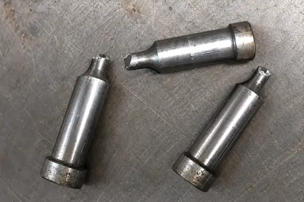
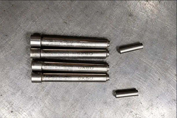
A large punch may tolerate some side loading and only show uneven wear. A slender punch, however, can bend under a relatively small lateral force. Repeated bending during thousands or millions of stamping cycles can gradually create fatigue cracks and eventually cause complete breakage.
Excessive working length is another common cause. For the same punch diameter, a longer unsupported section has much lower resistance to bending. This is why small punches with long straight working sections tend to fail more frequently.
Stress concentration at diameter transitions is also important. If a large shank changes suddenly into a small working section with a sharp corner, the local stress at the shoulder can become much higher than the average stress in the punch. Fatigue cracks often begin at this location.
Incorrect die clearance can further reduce punch life. Clearance that is too small increases cutting force, friction, and stripping force. Uneven clearance creates side loading, causing one side of the punch to carry more load than the other.
Some punches fail during the return stroke rather than during penetration. After punching, the sheet material can grip the punch tightly. Excessive stripping force, material adhesion, slug pulling, or insufficient stripper guidance can place additional tensile and bending loads on the punch.
Abnormal conditions such as slug stacking, foreign particles, die misalignment, or press accuracy problems can also create sudden impact loads and cause edge chipping or immediate punch failure.
4. How to Improve Punch Life Through Design
The main goal of punch design is to keep the punch carrying axial load as much as possible while reducing bending and side loading.
For small holes, the punch should have a large supporting section and only a short small-diameter working end. A-type or three-step A-type structures are often more stable than a long straight small-diameter punch.
A practical design can be summarized as:
Large Supporting Section → Smooth Transition → Short Working Section → Proper Guidance → Uniform Die Clearance
Sharp shoulders should be avoided where the diameter changes. A smooth transition radius helps distribute stress and reduces the chance of fatigue cracking at the punch root.
For slender punches, a stripper plate or guide plate can support the punch close to the sheet surface. This reduces the effective unsupported length and improves alignment.
Punch-to-die clearance should also be uniform around the entire cutting edge. If replacement punches repeatedly chip or break on the same side, the die alignment, punch plate, guide system, and clearance should be checked before changing the punch material.
For obround punches and other profile punches, special attention should be paid to the weaker direction of the cross-section because stiffness is not equal in every direction.
5. Common Punch Materials
Punch materials must provide a balanced combination of hardness, wear resistance, compressive strength, and toughness. A harder punch is not automatically a better punch, especially when the tool is exposed to bending or impact.
SKD11 / D2 is a widely used cold-work tool steel with good wear resistance and is suitable for many general punching applications.
DC53 is often selected when improved toughness is required while still maintaining high hardness and wear resistance.
SKH51 / M2 high-speed steel offers a useful balance of toughness and wear resistance and is commonly used for small-diameter or high-cycle punch pins.
Powder metallurgy tool steels provide excellent combinations of wear resistance, strength, and toughness and are often used in demanding high-volume stamping applications.
Carbide provides extremely high hardness and wear resistance and can achieve very long life in abrasive or extremely high-volume applications. However, carbide is more brittle and requires excellent alignment, stable guidance, and controlled impact loading.
For slender punch pins, toughness can be just as important as hardness.
6. Common Surface Treatments for Punch Pins
Surface treatment can reduce friction, adhesion, and wear and can therefore improve punch life when the base design is already correct.
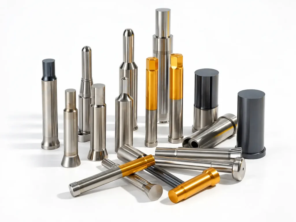
TiN coating is one of the most widely used PVD coatings. It improves surface hardness and wear resistance and can reduce friction in general steel stamping applications.
TiCN coating generally provides higher hardness and wear resistance than standard TiN and is often used in more demanding or high-cycle punching conditions.
TiAlN and AlCrN coatings provide good wear resistance and thermal stability and can be useful under higher-load or higher-temperature contact conditions.
DLC coating has a very low coefficient of friction and is particularly useful when stamping materials such as aluminum or copper that tend to adhere to the punch surface. Reduced adhesion can help lower stripping force and minimize galling.
Nitriding can increase surface hardness and wear resistance while maintaining a tougher core structure. It is commonly used on suitable tool steels where improved surface durability is needed.
Surface treatment should not be used as a substitute for proper punch design. If a punch is too slender, poorly guided, misaligned, or working with incorrect die clearance, even a high-performance coating will not solve the underlying breakage problem.
Frequently Asked Questions
Punch pins commonly break because of excessive unsupported length, punch-to-die misalignment, improper clearance, side loading, high stripping force, stress concentration, or insufficient punch toughness. Repeated lateral loading can also cause fatigue cracks and eventual failure.
Keep the small-diameter working section as short as possible, increase the supporting body diameter, use smooth transition radii, provide proper punch guidance, and maintain uniform punch-to-die clearance. For very slender punches, a guided stripper can significantly reduce unsupported length.
There is no single best material for every application. D2/SKD11 offers good wear resistance, M2/SKH51 provides a useful combination of toughness and wear resistance, and powder metallurgy steels are often used for demanding high-volume applications. Material selection should consider workpiece material, punch size, impact loading, wear, and production volume.
Clearance that is too tight increases punching force, friction, stripping load, and stress on the cutting edges. Uneven clearance can also create side loading. The correct clearance depends on sheet material, hardness, thickness, and required cut-edge quality.
No. Increasing hardness can improve wear resistance but may reduce toughness. A very hard punch subjected to impact or lateral loading can chip or fracture prematurely. Punch material should provide an appropriate balance between hardness, wear resistance, and toughness.
Coatings can reduce friction, wear, galling, and material adhesion, but they cannot correct excessive punch length, poor alignment, incorrect clearance, or insufficient core strength. Structural and die-condition problems should be corrected before relying on coatings to improve tool life.